2TLC172287M0201 Rev B 28 www.abb.com/jokabsafety
2015-09-17
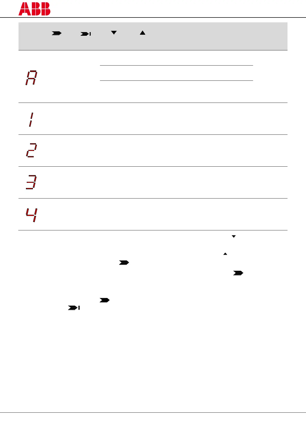
Last OK
Middle optics not OK
Each beam is over the min. operating
light reception threshold and the
number of beams over the light
reception threshold is between 0 and
25%
Each beam is over the min. operating
light reception threshold and the
number of beams over the light
reception threshold is between 25 and
50%
Each beam is over the min. operating
light reception threshold and the
number of beams over the light
reception threshold is between 50 and
75%
Each beam is over the min. operating
light reception threshold and the
number of beams over the light
reception threshold is between 75 and
100%
1) Keep the receiver in a steady position and adjust the transmitter until the yellow LED ( FIRST) turns off. This
condition shows the alignment of the first synchronisation beam.
2) Rotate the transmitter, pivoting around the lower optics axis, until the yellow LED ( LAST) turns off.
NB: Make sure that the green LED ( ) is on and steady.
3) Slightly turn both units both ways to find the limits of the area in which the green LED ( ) is steady and “4”
is displayed (Maximum alignment). Place both units in the centre of this area.
4) Fix the two units firmly using brackets.
Check that the green LED ( ) on the receiver is on when the beams are not interrupted. Then check that
the red LED ( ) turns on when one single beam is interrupted. This check shall be made with the special
cylindrical “Test Piece” having a suitable size for the resolution of the device used (see paragraph 3.3 –
“Checks after first installation”).
5) Switch the device off and on to normal operating mode.
The alignment level is also monitored during normal operating mode and visualized on the display (see
paragraph 8.2 – “Diagnostic messages”).
Once the AOPD has been aligned and correctly fastened, the signal on the display is useful both to check the
alignment and to show a change in the environmental conditions (presence of dust, light disturbance and so on).