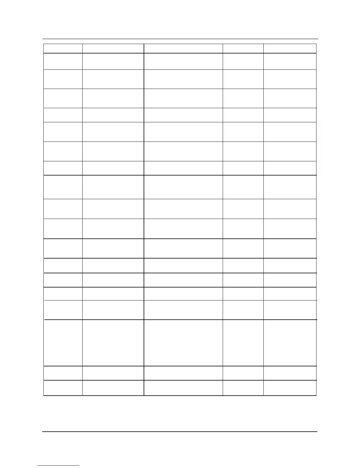
INDICATOR ISSUE RESOLUTION (C HE CK & CORRECT) RESET SOURCE
Low-Low Conce ntrati on i s bel ow Inf orma tion Only. Adjust Limits under When Component
Conce ntrati on Low-Low Setp oi nt the Setup tab as needed. reported.
Low Conce ntrati on i s bel ow Inf orma tion Only. Adjust Limits under When Component
Conce ntrati on Low Setpoint but above the Setup tab as needed. Reported
Low-Low Setp oi nt
High Concentration exceeds the I nf orma tion Only. Adjust Limits under When Component
Conce ntrati on High Setpoint but below the Setup tab as needed reported
High-High Setpoint
High-High Concentration exceeds the I nf orma tion Only. Adjust Limits under When Component
Conce ntrati on High-High Setpoint the Setup tab as needed reported
RF Low Limit Calculated response factor Inf orma ti on Only. Adjust Limits under When Component
out of range (low) (% of the Setup tab as needed. recalibrated
deviation from previous RF)
RF High Limit Calculated response factor I nf orma tion Only. Adjust Limits under When Component
out of range (high) % of the Setup tab as needed recalibrated
deviation from previous RF)
Retention Time Retention time is below Inf orma ti on Only. Adjust Limits under When Component
Low Low Setp oi nt the Setup tab as needed. Reported
Retention Time Retention time exceeds Inf orma tion Only. Adjust Limits under When Component
High High Setjpoint the Setup tab as needed. Possible reported
leak. Possible defective EPC pressure
sensor. Possi ble plugged inlet filter.
Validation Measurement out of range Inf orma tion Only. Adjust Limits under We n Component
(% of deviation from known the Setup tab as needed. Flows revali da ted
standard) incorrectly set. Defective EPC se nsor.
Missing No peak found matching a Inf orma ti on. Edit analysis as needed. When Analysis
Component component defined in the reported
analysis
Unkno wn Peak detected in the Che ck f lo ws. Verify correct operation When Analysis
Component analysis and not defined in operation of all ana lytical valves. Reported
the me tho d Verify sample flow to oven.
Sampl e Fl ow L os t Future functionality: Restore Sample flow. Replace s ample AOC Analysis
Sample f low is lost flow switch as necessary
Digin Check TCF Progr ammabl e Input See Digital inut TCF in Operating AOC Analysi s
checks Inst ructi o ns.
Psrs C he ck T CF Pressure Check failed See pressure check TCF in AOC Analysi s
Operati ng Instr ucti ons.
Invalid Analysis Analysis failed validation 1. From Analysis tab edit Analysis to AOC Analysi s
meet requireemnts.
2. User control led.
Analysis Aborted 1. Analysis does not 1. Check Pressure, Temperature AOC Analysis
complete analysis due to and/or Digit al In puts. Correct problem
temperature, pre ssure accordingly.
and/or di gital input 2. User control led.
programmed command. 3. Che ck o ven rel ate d indi cators for
2. User intervention using more information.
Stop Now command.
3. Related oven issues.
Offline Schedule Offline: Oven i s Inf orma ti on Only. Resets when oven AOC Schedule
powered down power is res tored.
Idl e Schedule Stopped or Inf orma ti on Only. AOC Schedule
pause d