106 Product manual - PVS-175-TL;A.1 Version
EN
• When the input voltage is sufficient to allow the connection to the grid, the inverter will check the grid
voltage, measure the isolation resistance of the photovoltaic field with respect to ground and performs
other auto-diagnostic checks. During the preliminary checks on the parallel connection with the grid,
the “Power” LED keeps flashing, the “Alarm” and “GFI” LEDs are OFF. The inverter will ONLY connect to
the grid if all parameters fall within the ranges foreseen by current regulations.
• If the outcome of the preliminary checks to grid synchronization are positive, the inverter connects and
starts to export power to the grid. The “Power” LED remains fixed on while the “Alarm” and “GFI” LEDs
are OFF.
NOTE – D To address any problems that may occur during the initial stages of operation of the
system and to ensure the inverter remains fully functional, you are advised to check for any
firmware updates in the dedicated section of web user interface (“SERVICE TOOLS menu”),
via Installer for Solar Inverters APP or in the download area of the website www.abb.com/
solarinverters or at https://registration.abbsolarinverters.com (refer to ““Registration
website” and “Admin Plus token”” paragraph).
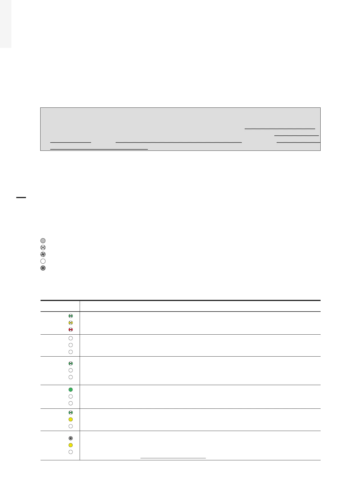
7.3 LEDs behaviour
All possible LED (08) activation combinations are shown in the following table. In particular, each LED
could behave in one of the following ways:
= LED on
= LED flashing slow (2 seconds on / 2 seconds off)
= LED flashing fast (0.2 seconds on / 0.2 seconds off)
= LED off
= Any one of the conditions described above
The following table shows all the possible activation combinations of “Power” “Alarm” and “GFI” LEDs on
the LED panel (08) according to the operating status of the inverter.
LED status Operating state
green:
yellow:
red:
Firmware programming
The inverter firmware is being programmed (never turn off the inverter during this
phase).
green:
yellow:
red:
Night mode (inverter automatically switches off)
The inverter is in night time switch-off mode (input voltage less than 70% of the set
start-up voltage and AC grid is missing).
green:
yellow:
red:
Inverter initialization / Waiting Sun
This is a transitional state due to verification of the operating conditions. During
this stage the inverter checks that the conditions for connecting to the grid are
met.
green:
yellow:
red:
The inverter is connected and is feeding power into the grid
Normal operation. During this stage, the inverter automatically tracks and analyses
the photovoltaic generator’s maximum power point (MPP).
green:
yellow:
red:
Missing grid
Indicates lack of grid voltage. This condition does not allow the inverter to connect
to the grid.
green:
yellow:
red:
Warning indication: (W message codes) or Error: (E message codes)
- Indicates that the inverter control system has detected a warning (W) or error (E).
It is possible to identify the type of problem generated in the dedicated section of
Web User Interface (“INVERTER LOG menu” section).
 Loading...


