155Maintenance
EN
8.11.2 Alarm Messages of the Inverter
In order to understand and resolve warning (Wxxx) or error (Exxx) signals that appear in the “INVERTER
LOG menu” or “MAIN menu” sections of the Web User Interface follow the table given in the following
paragraph.
The equipment can notify errors/warnings in the Event or Dashboard sections of the Web User Interface
only if the input voltage is greater than the Vdcmin voltage (POWER Led flashing or lit; refer to “LEDs
behaviour” paragraph).
NOTE – D The following table gives the complete list of errors/warnings relating to string
inverters. Some error/warning codes may not be used depending on the inverter model
installed.
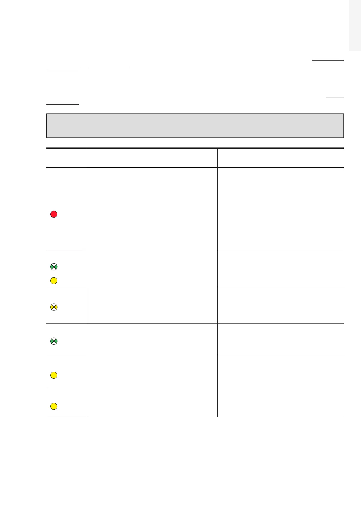
- Error code
- Error message
- LED status
Name of Alarm and Cause Solution
- No code
- Ground F
- Red LED
Ground fault of photovoltaic generator:
The alarm is generated when a leakage current to
ground is detected in the DC section of the system.
• Measure the isolation resistance using a
megohmmeter positioned in the photovoltaic array
(positive terminal short-circuited at the negative
pole) compared to ground. The measurement is
strongly influenced by the environmental
conditions, so must be made under the same
conditions in which the error occurred.
- If the value measured is lower than 1 megaohm, a
check must be carried out by a technician/installer
on the photovoltaic generator to identify and
eliminate the problem.
- If the value measured is higher than 1 megaohm
and the error signal persists, contact customer
assistance.
- No code
- Missing Grid
- Flashing
green LED
- Yellow LED
Missing Grid:
The inverter does not detect grid voltage (AC side).
• Check the grid voltage on the inverter's AC
terminal block.
- Should it be absent, check any protection work on
the line and the presence of grid voltage on the
supply point.
- No code
- Memory fault
- Flashing
yellow LED
Memory fault:
The inverter has detected a communication problem
with the memory board on which the inverter saves
the daily value of energy produced.
• Remove the memory board and check the welding
of all the connector's terminals. Subsequently
reinsert the memory board and check that it is
correctly inserted into the dedicated slot
- If the signal persists also following the above
checks, contact customer assistance.
- No code
- Waiting Sun
- Flashing
green LED
Waiting Sun:
The inverter goes into the “Waiting Sun” stage when,
following a W001 and/or W002 warning, the voltage
from the photovoltaic generator is less than the
activation voltage (Vstart).
• Check the input voltage on the inverter.
- If it does not exceed Vstart, check for the
presence of sufficient irradiation and the correct
composition of the system.
- If it exceeds Vstart, contact customer assistance
- W001
- Sun Low
- Yellow LED
Insufficient irradiation (Low input voltage on
switching on the inverter):
Incorrect configuration of the PV generator or an “on
the limit” configuration for the inverter's minimum
input voltage.
• Check the input voltage on the inverter.
- If it does not exceed Vstart, check for the
presence of sufficient irradiation and the correct
composition of the system.
- If it exceeds Vstart, contact customer assistance
- W002
- Input UV
- Yellow LED
Insufficient irradiation (Low input voltage on
switching off):
Incorrect configuration of the photovoltaic
generator or an “on the limit” configuration for the
inverter's minimum input voltage.
• Check the input voltage on the inverter.
- If it does not exceed Vstart, check for the
presence of sufficient irradiation and the correct
composition of the system.
- If it exceeds Vstart, contact customer assistance
 Loading...


