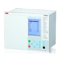
IEC15000270 V1 EN-US
Figure 34: Display layout
1 Path
2 Content
3 Status
4 Scroll bar (appears when needed)
The function key button panel shows on request what actions are possible with the
function buttons. Each function button has a LED indication that can be used as a
feedback signal for the function button control action. The LED is connected to the
required signal with PCM600.
1MRK 505 370-UUS A Section 5
Local HMI
Busbar protection REB670 2.2 ANSI 99
Application manual

 Loading...