RHD250 to 4000 (Contrac) ELECTRICAL ROTARY ACTUATOR | SEI/RHD250/4000-EN REV. A 19
Brake adjustment
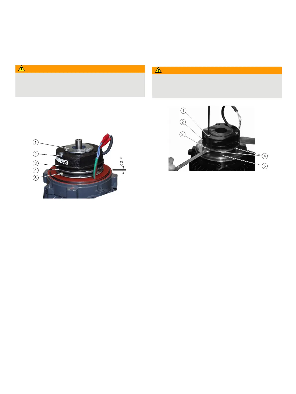
Brake of motor series 1
Risk of injury
Note that the actuator position may be changed accidentally
by the external load on the drive when the brake is released or
Note
Do not turn the slotted nut
1. It preloads the brake spring. Any
disadjustment may reduce the brake
force and thus disable the brake to hold the actuator in position!
Slotted nut
Socket head screws
Coil body
Brake disk
Counter nuts
Figure 32: Brake of motor series 1
In automatic mode the brake is permanently released. Therefore,
it is not exposed to wear and does usually not require any re-
adjustment. The gap between coil body and brake disk should be
approx. 0.2
+0.1
mm (0.008 to 0.012 inch). To check the gap
switch-off the voltage supply and put a thickness gauge
between the coil body
3 and the brake disk 4. If the brake
requires an adjustment (e. g. after replacement) proceed as
follows:
1. Disconnect the voltage supply.
2. Remove the brake cover.
3. Loosen the socket head screws
2.
4. Put a thickness gauge (0.2 mm) between the coil body
3
and the thrust plate
4.
5. Turn the counter nuts
5 until the thickness gauge is
tautly between coil body
3 and thrust plate 4.
6. Tighten the socket head screws
2 evenly.
Brake of motor series 2
Risk of injury
Note that the actuator position may be changed accidentally
by the external load on the drive when the brake is released or
Socket head screws
Coil body
Thrust plate
Brake disk
Base plate
Figure 33: Brake of motor series 2
In automatic mode the brake is permanently released. Therefore,
it is not exposed to wear and does usually not require any re-
adjustment. The gap between coil body and brake disk should be
approx. 0.2
+0.1
mm (0.008 to 0.012 inch). To check the gap
switch-off the voltage supply and put a thickness gauge
between the coil body
2 and the brake disk 4. If the brake
requires an adjustment (e. g. after replacement) proceed as
follows:
1. Disconnect the voltage supply.
2. Remove the brake cover.
3. Turn the socket head screws
1 completely out.
4. Take the brake body
2 off.
5. Turn the hexagon nuts
4 cw until they are in touch with
the brake body
2.
6. Put the brake body
2 onto the shaft and tighten the
screws
1; hand screwed.
7. Turn the hexagon nuts
4 ccw until they are in touch with
the base plate
5.
8. Evenly turn the socket head screws
1 approx 1/3 turn
ccw (approx 120°); this also lifts the hexagon nuts
4.
9. Turn the hexagon screws
4 until they are in touch with
the brake body
5.
10. Check the gap between brake body
2 and thrust
plate
3 using a thickness gauge 0.2
+0.1
mm
(0.008 to 0.012 inch).