8 RHD250 to 4000 (Contrac) ELECTRICAL ROTARY ACTUATOR | SEI/RHD250/4000-EN REV. A
4 Maintenance
Safety instructions
Risk of injury due to live parts!
Risk of death or serious injuries due to electricity and
unexpected machine movements. In automatic mode the
motor is always under power, even at standstill.
• When working on the actuator or the related subassembly,
switch off the supply voltage for the electronic unit and
separate anti-condensation heater (option), and take
precautions to prevent unintentional switch-on.
Repair and maintenance activities may only be performed by
authorized customer service personnel.
When replacing or repairing individual components, use original
spare parts.
General
Contrac actuators feature a robust construction. As a result,
they are highly reliable and require minimal maintenance. The
maintenance intervals depend upon the effective load and are
therefore not specified here.
The built-in microprocessor evaluates the actual load factors
(e.g. torques, forces, temperatures, etc.) and derives the
remaining operating time until the next routine maintenance is
required.
Use the configuration program to view this information.
Apart from the load dependent maintenance intervals
determined by the microprocessor we recommend routine
maintenance at least every 10 years.
The following description of the maintenance work provide that
the actuator is disconnected from the damper and that all
electrical supply is disconnected.
Lever
Lever removal
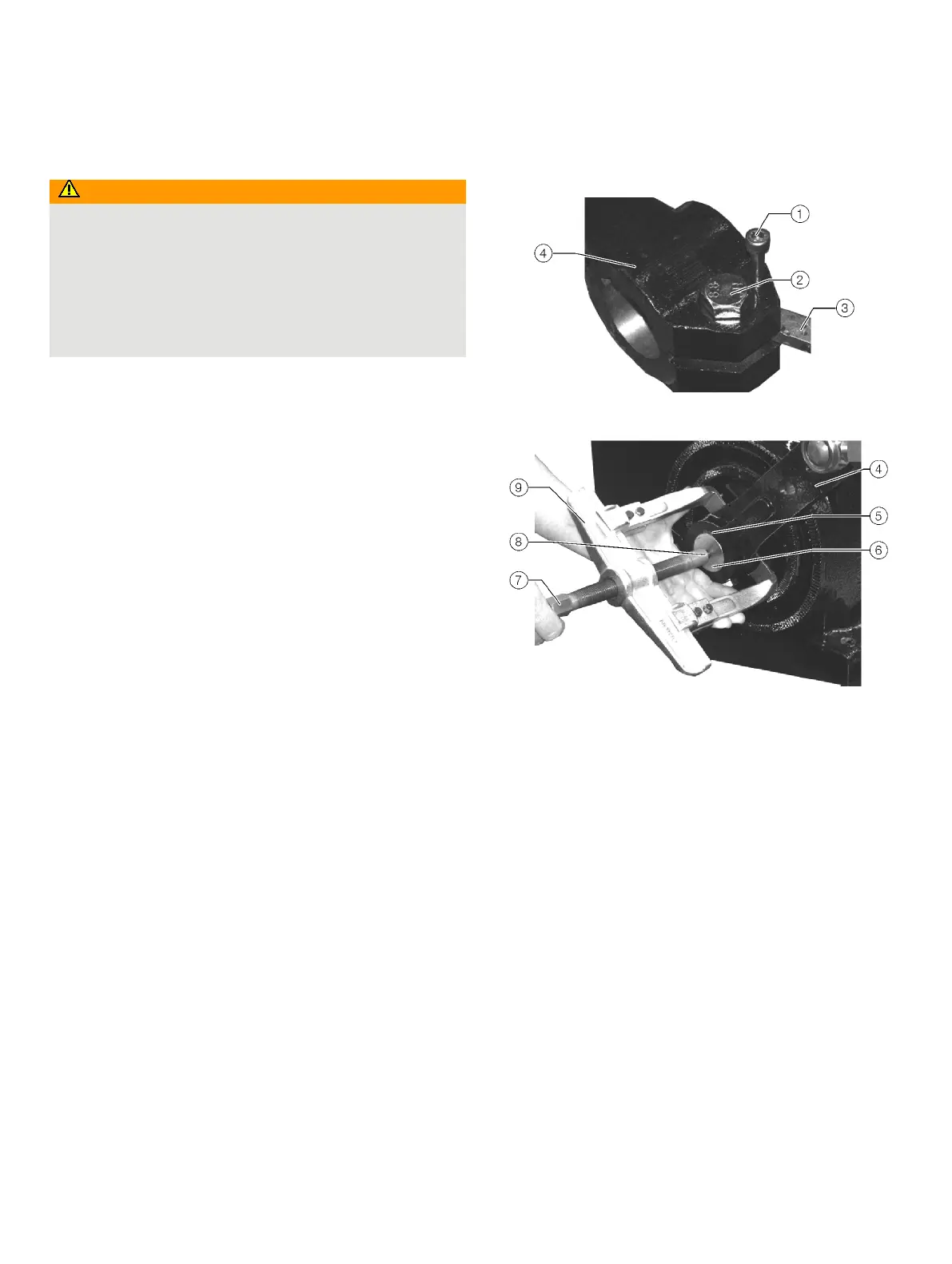
Figure 3: Lever mounted on the shaft
Figure 4: Use of draw-off tool for lever removal
In some case it may be useful to detach the linkage bar from the
ball-and-socket-joint, however, it is not absolutely necessary.
Refer to Figure 3 and Figure 4 for the removal procedure:
1. Loosen the clamping screw
2.
2. Use an expanding screw
1 to spread the lever seat.
3. Push a counterpart
3 (soft metal) into the lever gap in
order to protect the expanding screw thread.
4. Put the claws of the drawing tool
9 behind the lever 4
and place the bolt end
8 on the shaft 6.
5. Put an appropriate tool onto the hexagon end
7 of the
drawing tool bolt.
6. Turning the bolt clockwise will pull the lever from the
shaft end.