RHD250 to 4000 (Contrac) ELECTRICAL ROTARY ACTUATOR | SEI/RHD250/4000-EN REV. A 27
6 Exchange of position sensor
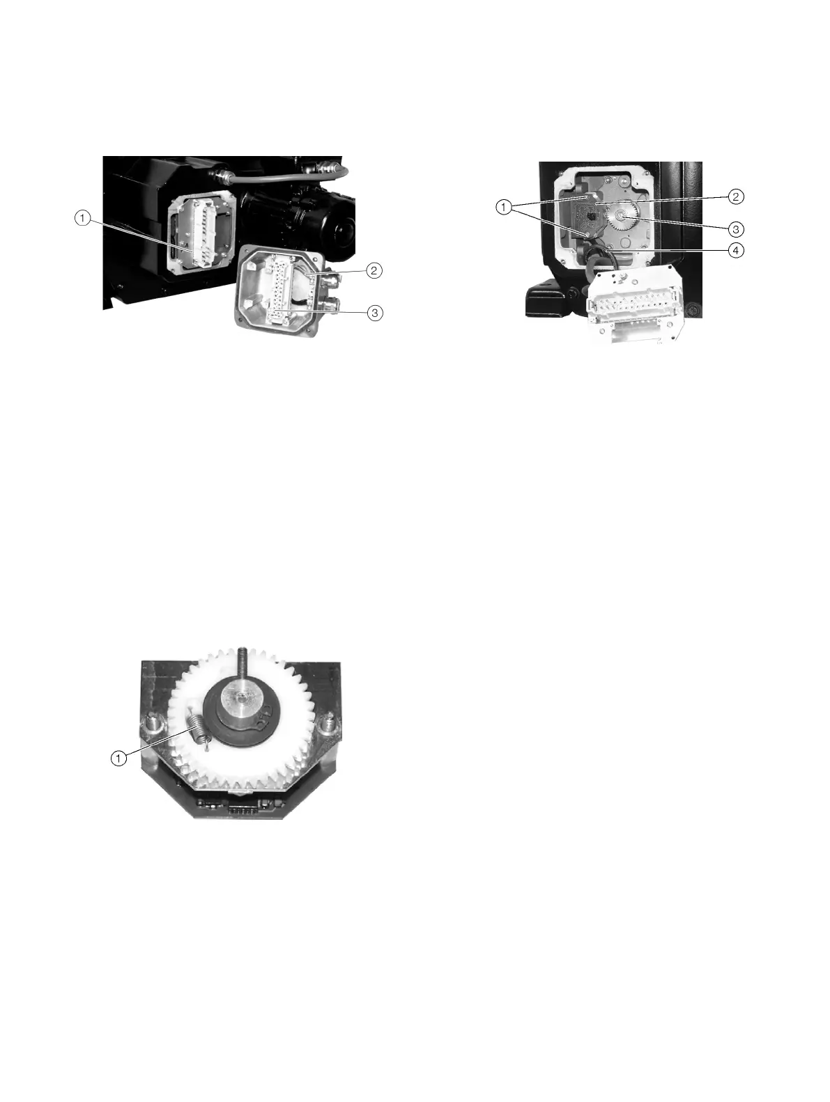
Dismounting
Male connector
Plug housing
Female connector
Figure 47: Example shows RHD500 (without heater)
1. Drive actuator into 50% position (referred to rated actuator
operating range).
2. Delete the current position settings by pressing the 2 drive
buttons on the LCP for at least 5 sec.
3. Switch-off the voltage supply.
4. Disconnect electrically.
5. Remove male connector.
6. Loosen both fastening screws
1 of position sensor (Figure
51) and take the sensor out.
7. Detach the plug from the sensor pcb.
Mounting
Tension spring
Figure 48: Position sensor
The toothed gear pair of the position sensor is held in place by a
tension spring
1, to ensure backlashfree motion when the
direction of rotation is reversed.
1. Set the stop pin to the center position, as shown in Figure
50.
Fastening screws
Position sensor
Shaft gear
Sensor cable
Figure 49: Mounting position (Example shows RHD500)
2. Align the sensor and its gears with the actuator; set the first
toothed gear in 09:00 o’clock position (Figure 51) onto the
drive shaft gear
3.
3. Slightly move the sensor back and forth to pre-tension the
toothed gears with the difference ‘z’ until the second
toothed gear snaps in.
4. Fasten the screws
1 tightly.
5. Fasten sensor cable plug on sensor pcb
6. For the remaining assembly steps follow the disassembly
procedure in reverse order
7. After mounting is completed readjust the actuator range as
described in the setup section of this manual