EasyManua.ls Logo

ABB XFC G5 - Install Battery and Charger; Install the Battery; Install the Solar Panel

ABB XFC G5
79 pages
Print Icon
To Next Page IconTo Next Page
To Previous Page IconTo Previous Page
Loading...
2106001MNAA | XSERIES G5 START UP GUIDE | 37
Table 5-1: XFC AI Pinouts
Input
Pin
Description
AI-1
1
(+) Input signal
(-) Input ground
2
AI-2
3
(+) Input signal
(-) Input ground
4
The XRC has five onboard analog inputs. Determine the AI and refer to the
pinout table for wiring.
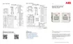
Figure 5-2 shows the XRC analog input terminals and the input mode
selector jumpers. Use these jumpers to set the analog input for the type of
input signal expected (voltage or current). Follow the legend to set the
correct AI to the correct mode. By default, all analog inputs are set for
voltage inputs (0 -10 V).
Figure 5-2: XRC AI terminals and input mode selector jumpers
Table 5-2: XRC AI Pinouts
Input
Pin
Description
AI-1
1
(+) Input signal
2
(COM) Input ground
AI-2
3
(+) Input signal
4
(COM) Input ground
AI-3
5
(+) Input signal
6
(COM) Input ground
AI-4
7
(+) Input signal
8
(COM) Input ground
AI-5
9
(+) Input signal
10
(COM) Input ground

Table of Contents

Other manuals for ABB XFC G5

Related product manuals