Getting Started
Installing your analyzer
Place your Anion 2 Analyzer on a dry, clean, stable and horizontal surface. Make sure that the analyzer is located with sufcient surrounding airspace, at least 5
inches on each side. Placement of Anion 2 Analyzer should allow easy disconnection from the wall outlet at any time. Acclimate the analyzer to ambient operating
temperature (15-32°C, 59-89°F) before use.
The analyzer might be impaired by:
• Condensing humidity and water
• Heat and large temperature variations
• Direct sunlight
• Vibrations (e.g. from centrifuges and dishwashers)
• Electromagnetic radiation
• Movement of the analyzer during processing of a test cartridge
Connecting power supply
- Connect the power cable to the power supply.
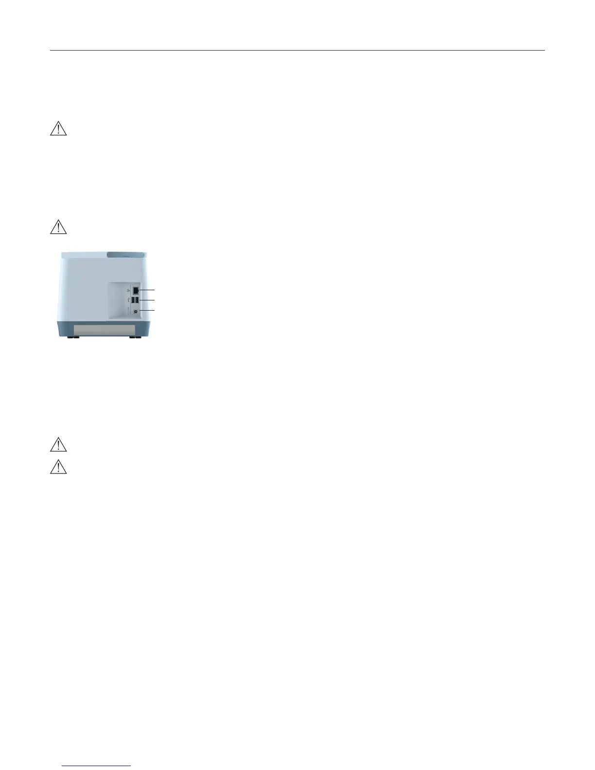
- Insert the plug from the power supply into the power socket (Figure 3) in the back of the analyzer.
- Plug in the power supply to a wall outlet.
Only use the power supply and cable supplied with Anion 2 Analyzer. Any other power supplies or cables can damage the analyzer and may cause possi-
ble hazards.
1
2
3
Figure 3
1 Ethernet port for connection to LIS/HIS/EMR systems. Use shielded cable.
2 USB-A connectors for printer, USB ash and barcode reader.
3 Power input for power supply connection
Connecting additional equipment
Optional equipment, not provided with your Anion 2 Analyzer are:
• External barcode reader – for reading barcoded sample or operator identication.
• Printer – for optional print out of test results.
For additional information regarding barcode reader and printer specications, please contact your local Anion 2 supplier.
Connecting the equipment should be done while the analyzer is powered off.
All equipment connected to the USB and/or Ethernet ports must have double or reinforced insulation from mains to prevent the risk of electric shock.
Connectivity
Anion 2 Analyzer can reliably transfer test information to an information system. Use the Ethernet cable to interface the Anion 2 Analyzer to an information system.
Anion 2 Analyzer automatically transfers patient and control results to a connected LIS/HIS/EMR system via TCP/IP networking using the protocols POCT1-A,
HL7, ASTM 1381-85 (low level) or ASTM 1394-97 (high level), selectable by conguration. ASTM and HL7 protocols support the transfer of patient and QC
results. POCT1-A protocol supports in addition functions such as device lockout and operator list management. Operator conguration allows for protection of
connectivity settings. When operator conguration is set to operator ID with verication, the conguration of connectivity will only be available for operators at
supervisor level. For relevant information, see chapter “Operator conguration”, page 14.
When you export data that contains patient information, it is your responsibility to comply with your local regulations on protection of personal health information.
Anion 2 Analyzer POCT1-A, ASTM and HL7 communication protocols are available at www.alere.com or by contacting your local Anion 2 supplier.