Ins t a ll i n g a n d co n n ec t i n g | Se t t ing t h e s wit c hin g p o i nts o f a m ec h a nic a l h o is t l im i t s wi t c h
22
SETTING THE SWITCHING POINTS
OF A MECHANICAL HOIST LIMIT
SWITCH
ONLY WITH A MECHANICAL HOIST
LIMIT SWITCH
This section only applies to chain hoists with a
mechanical hoist limit switch of the sizes GM4,
GM6 and GM8.
Overview:
Size
Number of falls
Hook path
Mechanical hoist limit
switch
Switching hysteresis B
Hook path per
revolution [mm]
Hook path per revolution
of block adjustment [mm]
GM4 1 ≤8 m
≥9 m
GPK 48.2
GPK 205.2
28
118
58
251
14
58
GM4 2 ≤4 m
≥5 m
GPK 48.2
GPK 205.2
14
59
29
126
7
29
GM6 1 ≤10 m
≥11 m
GPK 48.2
GPK 205.2
34
145
72
310
17
72
GM6 2 ≤5 m
≥6 m
GPK 48.2
GPK 205.2
17
73
36
155
8
36
GM8 1 ≤14 m
≥15 m
GPK 48.2
GPK 205.2
49
207
103
440
24
103
GM8 2 ≤7 m
≥8 m
GPK 48.2
GPK 205.2
25
104
52
220
12
51
Outer white adjusting
screw
(lower switching point)
Middle white adjusting
screw
(upper switching point)
Black adjusting screw
(block adjustment)
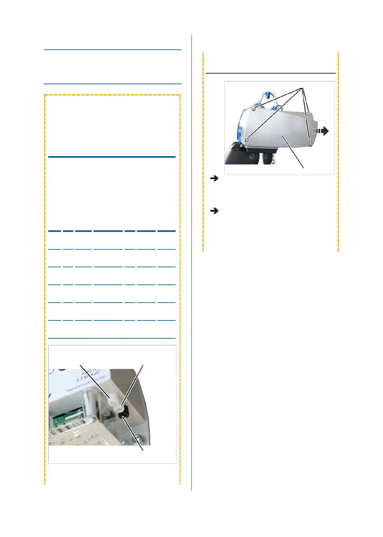
UNSCREWING THE MOTOR COVER
Fillister-head screws
Motor cover
Unscrew the motor cover from the housing.
The fillister-head screws are secured by O-
rings and thus do not fall out of the motor
cover.
Secure the motor cover.
The power supply must remain switched on
while setting the switching points.