Ins t a ll i n g a n d co n n ec t i n g | Se t t ing t h e s wit c hin g p o i nts o f a m ec h a nic a l h o is t l im i t s wi t c h
23
SETTING THE UPPER SWITCHING
POINT
Raise the load hook to the desired switching
point.
─ Bottom block or hook assembly must not
come into contact with the housing.
─ The friction clutch must not be triggered.
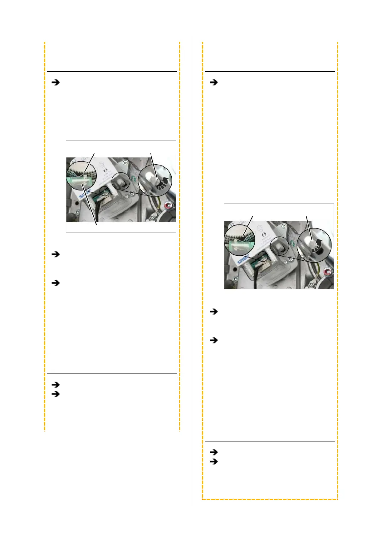
Control cam
Middle
adjusting screw
Microswitch
─ The upper switching point is set with the
middle adjusting screw.
If necessary: Turn the adjusting screw until
the control cam is to the left of the
microswitch. It should not be either directly
on or to the right of the microswitch.
Turn the adjusting screw to the left until the
control cam presses in an anti-clockwise
direction against the microswitch and an
audible click is heard.
─ Turn the adjusting screw to the right (the
control cam turns clockwise) to move the
switching point upwards.
─ Turn the adjusting screw to the left (the
control cam turns anticlockwise) to move
the switching point downwards.
CHECKING THE SETTING
Lower the load hook.
Raise the load hook at slow as well as fast
lifting speed and check that the load hook
halts at the correct hook position.
● The upper switching point is set.
SETTING THE LOWER SWITCHING
POINT
Lower the load hook to the desired lower
switching point.
─ The load hook must not come into contact
with the floor of building.
─ The chain must not be slack.
─ The C-link in the chain box must not come
into contact with the housing.
This would trigger the friction clutch and
then damage it in regular movement.
─ The hook path (distance between the
highest hook position and the lowest hook
position) must not be greater than specified
on the type plate.
Control cam
Outer
adjusting screw
─ The lower switching point is set with the
outer white adjusting screw.
If necessary: Turn the adjusting screw until
the control cam is to the right of the
microswitch. It must not be on the left of the
microswitch or exactly on it.
Turn the adjusting screw to the right until
the control cam presses in a clockwise
direction against the microswitch and an
audible click is heard.
─ Turn the adjusting screw to the right (the
control cam turns clockwise) to move the
switching point upwards.
─ Turn the adjusting screw to the left (the
control cam turns anticlockwise) to move
the switching point downwards.
CHECKING THE SETTING
Raise the load hook.
Lower the load hook at slow as well as fast
lifting speed and check that the load hook
halts at the correct hook position.
● The lower switching point is set.