Ins t a ll i n g a n d co n n ec t i n g | Se t t ing t h e s wit c hin g p o i nts o f a m ec h a nic a l h o is t l im i t s wi t c h
24
ONLY WITH A MECHANICAL HOIST
LIMIT SWITCH
SHIFTING BOTH SWITCHING
POINTS TOGETHER (BLOCK
ADJUSTMENT)
If both switching points are moved equally, both
switching points can be set at the same time.
Control cam
Black
adjusting screw
Turn the black adjusting screw to the left or
right to set both switching points at the
same time.
─ Turn the adjusting screw to the right (the
control cam turns clockwise) to move the
switching point upwards.
─ Turn the adjusting screw to the left (the
control cam turns anticlockwise) to move
the switching point downwards.
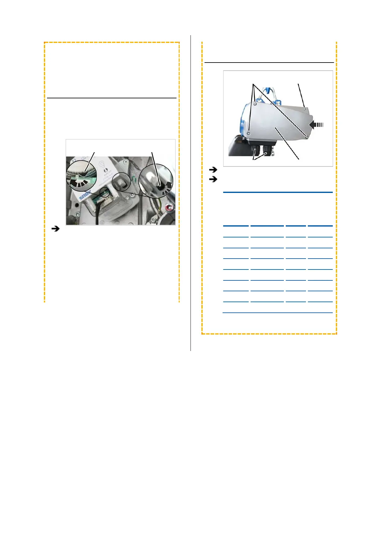
CLOSING THE CHAIN HOIST
Long fillister-
screws Short fillister-head screw
Bayonet coupling Motor cover
Hold the motor cover on the housing.
Note the different screw lengths and screw
in the fillister-head screws.
Size
Size and
length
Number
Tightening
torque
GM2 M5x65 3x 4 Nm
GM2 M5x45 1x 4 Nm
GM4 M5x60 3x 4 Nm
GM4 M5x50 1x 4 Nm
GM6 M8x110 3x 15 Nm
GM6 M8x60 1x 15 Nm
GM8 M10x95 3x 20 Nm
GM8 M10x50 1x 20 Nm