Ins t a ll i n g a n d co n n ec t i n g | I n s tal l a tio n o v e r vie w
16
INSTALLATION OVERVIEW
The following sections show how the chain hoist is
installed.
─ First, the suspension bracket of the chain hoist
is prepared and the chain hoist is attached to
the supporting structure. See page 16.
─ Then, the bayonet connector is connected to
the connecting cable and the connecting cable
is inserted into the chain hoist. See page 18.
─ Then the chain box is installed. See page 20
─ Finally, the chain is lubricated. See page 21.
─ Only with chain hoists with a hoist limit switch:
Lastly, the switching points of the mechanical
hoist limit switch (page 22) or the electronic
hoist limit switch (page 25) and, if applicable,
the intermediate switching point of the
electronic hoist limit switch (page 28) are set.
INSTALLING THE CHAIN HOIST
ONLY FOR GM2 AND GM4
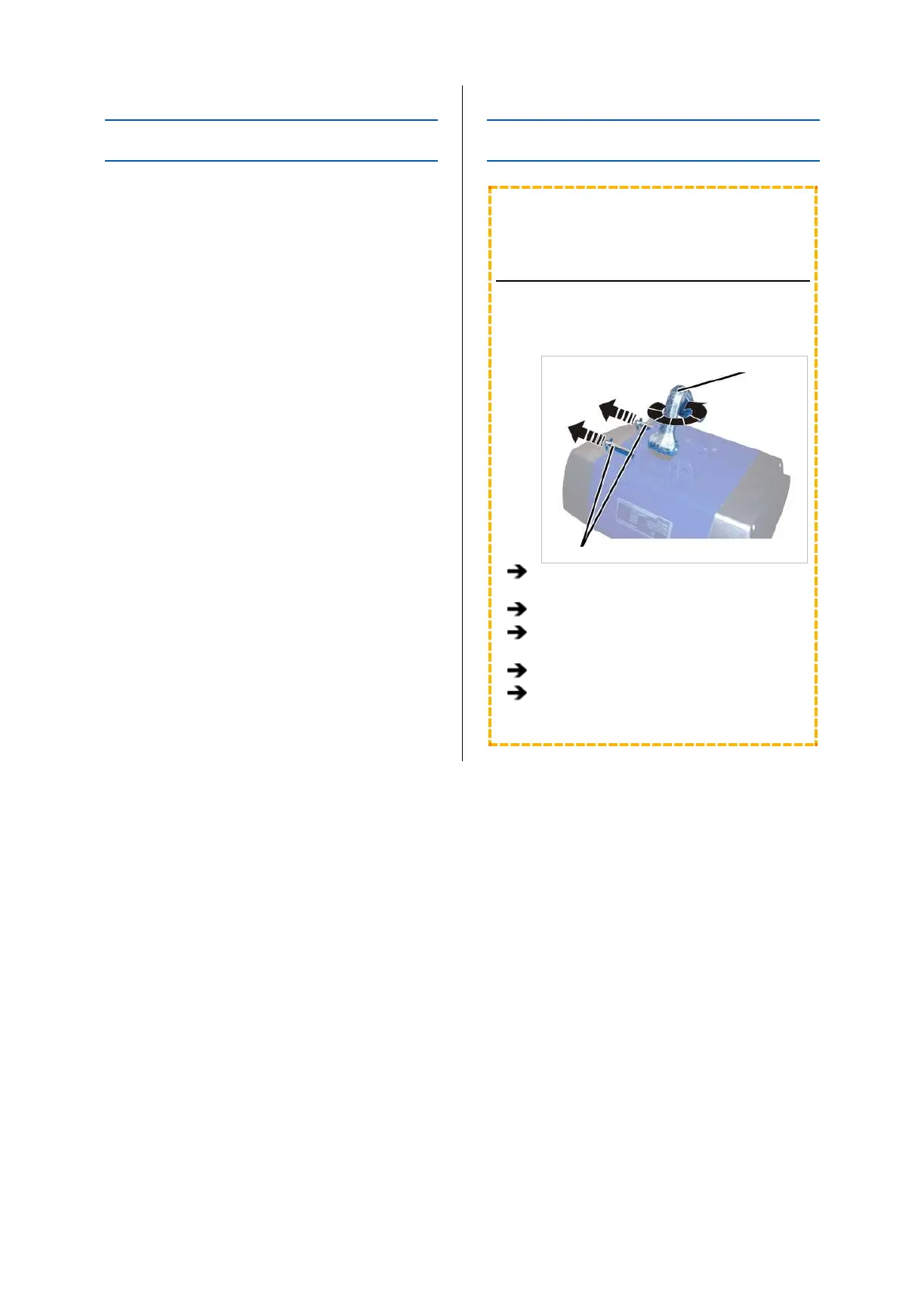
TURNING THE SUSPENSION
BRACKET BY 90° OR REMOVING IT
Depending on the installation site, the suspension
bracket can be turned by 90°.
Suspension bracket
Bolt
Detach the SL safety clip from each of the
bolts (2x).
Pull out the bolt.
Pull out the suspension bracket, turn it 90°
and reinsert it.
Insert the bolt.
Secure the bolts with the SL safety clips (1x
each).