Ma in t e n an c e | Rep l a cin g t h e bra k e ro tor
71
ONLY FOR GM6 (GM6 WITH CHAIN
BOX WITH METAL FRAME) AND
GM8
The illustrations show a chain box being installed
on the GM8 chain hoist. Installation on a GM6
chain hoist is very similar.
INSTALLING THE CHAIN BOX
Inner hole Bolt
Chain box SL safety clip
Place the chain in the chain box.
Turn the chain box as shown in the figure
(bar facing outward).
Use the bolts to install the chain box on the
chain hoist.
─ For GM6 and chain box with metal frame:
Use a bolt to fix the chain box to the chain
hoist. Use the inner holes of the suspension
strap. The outer holes of the suspension
strap remain free.
─ For GM8: Use a bolt to fix the chain box to
the chain hoist. Use the inner holes of the
suspension strap. The buffer is fixed to the
outer holes of the suspension straps.
Secure the bolts with the SL safety clips
(2x).
REPLACING THE BRAKE ROTOR
If the brake rotor on the chain hoist is thinner than
permitted, the brake rotor must be replaced.
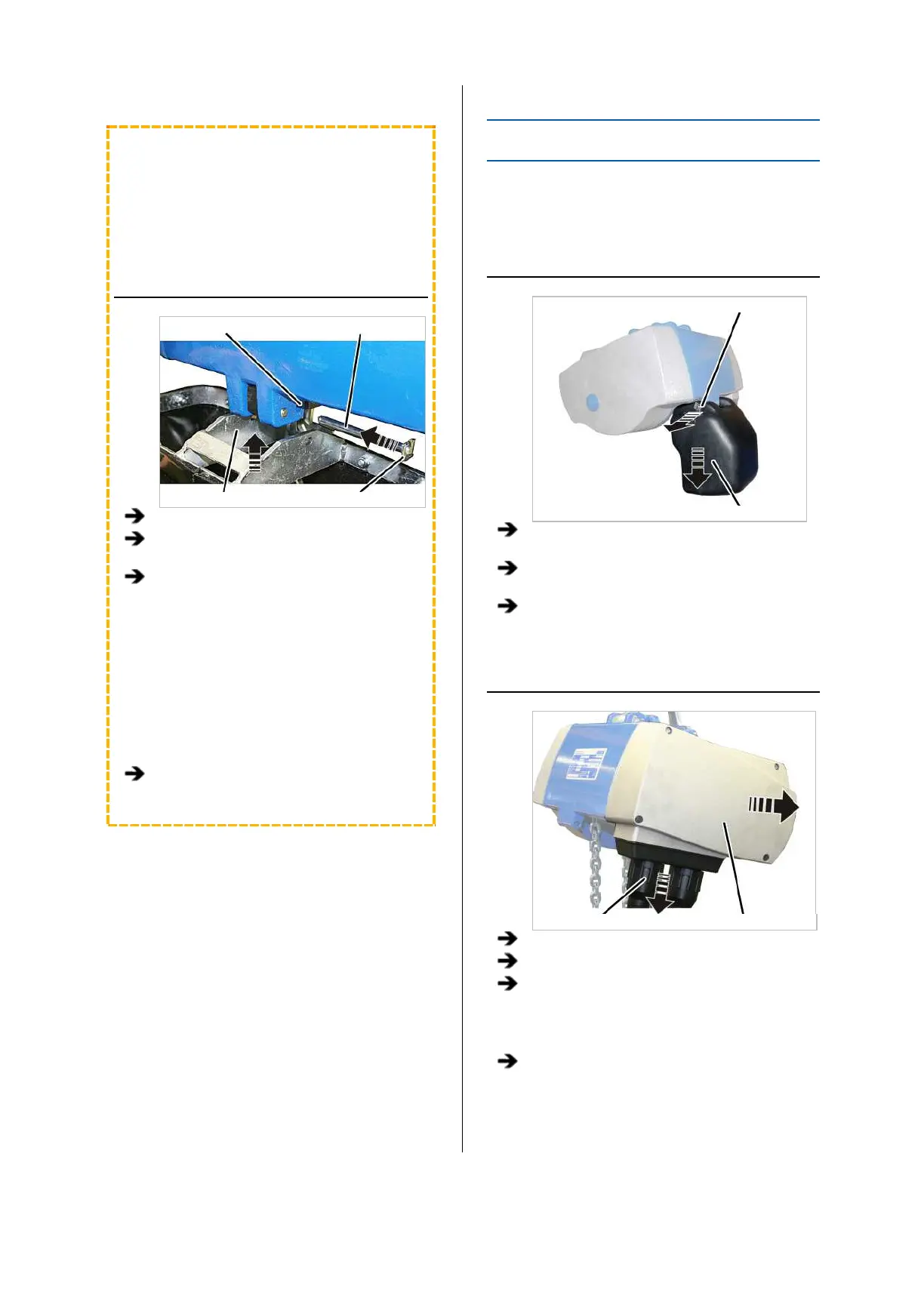
REMOVING THE CHAIN BOX
Bolt
Chain box
Release the SL safety clip(s) (1x or 2x) from
the bolt.
Hold the chain box firmly and pull out the
bolt(s) (1x or 2x).
Remove the chain box.
OPENING THE CHAIN HOIST
Bayonet nut Motor cover
Release the bayonet nuts.
Detach the connection cable and control cable.
Unscrew the motor cover from the housing.
● The fillister-head screws are secured by O-
rings and thus do not fall out of the motor
cover.
Detach the couplings of the hoist motor and
brake from the control in the motor cover.