129
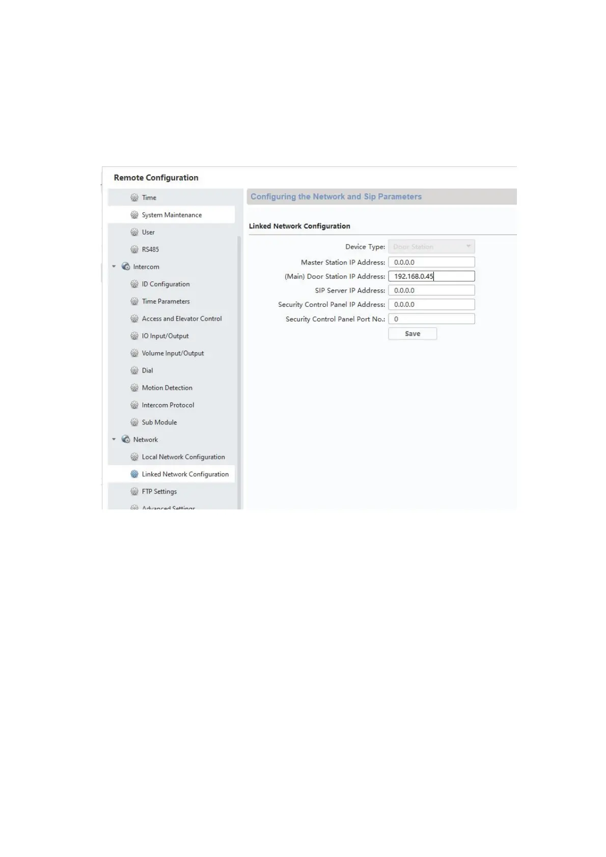
5) After successful restart, you will still need to assign the main doors for the back door. To
do this, enter and save the IP address of the main door station under “Network” /
“NetConfig SIP” under “(Main)Outdoor IP Address”.
Attention: The menu “(Main) Outdoor IP Address” will only appear if you have properly
completed step 4).
6) Setup for a back door is now complete. Now if a call button is pressed at the back door,
the monitor will show that the call was started at a back door. Under “LIVE IMAGE” you
can now directly access the video image of the back door on the monitor and open the
doors.
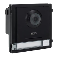
9.3 Setting up extended call buttons (TVHS20020) for multi-family homes
Up to 49 call buttons can be used for multi-family homes via the additional module
(TVHS20020(S)). The extension module is connected directly to the main video module via
connecting cables.
If only one additional call button module is used, the installation can be done without the ABUS
CMS software.
The main door module is by default the bell with “Apartment number 1”. The extension module
TVHS20020 is automatically set to apartment number 2–7. The “apartment” here corresponds to
a separate residence.
 Loading...