82
English
3. Installation
Make sure that all accessories and parts listed above are present in the scope of delivery. An Ethernet cable
is required for camera operation. This Ethernet cable must meet UTP Category 5 (CAT 5) specifications and
must not be longer than 100 metres.
3.1 Power supply
Before starting installation, ensure that the mains voltage and the rated voltage on the camera are identical.
3.2 Installing the camera
Firstly, the supplied base is fastened to the bottom of the camera. The plate is then aligned to the pre-defined
screw openings and fastened with the screws provided.
IMPORTANT!
The camera must be disconnected from the mains power during installation.
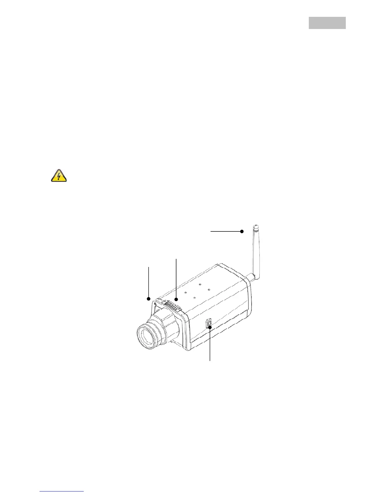
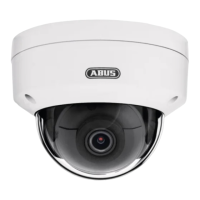
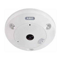
4. Camera description
4.1 Front view
Focus ring: Adjust the camera focus (image sharpness) by turning the ring.
Power LED: The LED is lit when in operation.
Network LED: When the camera is connected to a network, the LED flashes during data exchange.
Light Sensor
WLAN