83
English
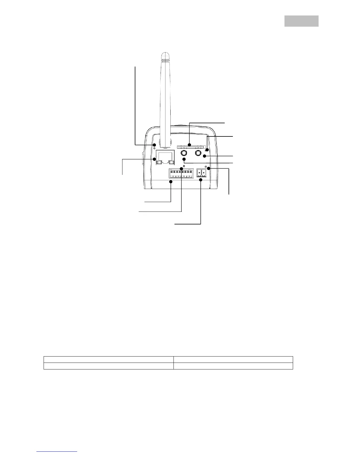
4.2 Rear view
Alarm input / output: One alarm input / output (see diagram below).
LAN interface: Used for establishing a network connection via the RJ-45 plug.
Audio output: Audio output via connected loudspeakers (two-way audio).
Audio input: Used for connecting a separate microphone.
Reset: Manual restart or reset to factory settings (see table).
Power supply: Connection for 12 V PSU.
WLAN antenna: Used for establishing a wireless network connection (WLAN 802.11 b/g).
Camera reset:
Reset button pressed once briefly Camera is restarted
Reset button held down for 10 seconds Camera reset to the factory settings
Power LED
Power connector
SD-Card-Slot
I/O terminal