84
English
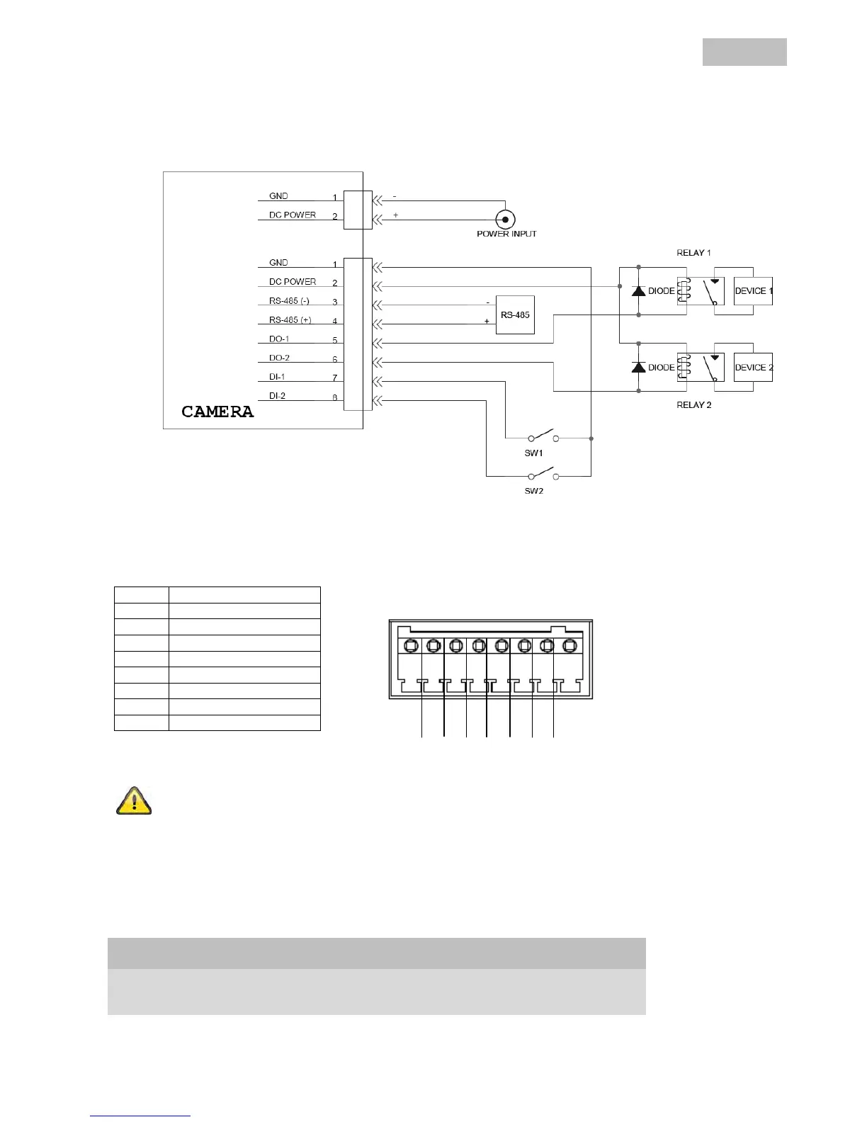
4.3 Alarm input and output
I/O Connector
PIN Description
1 Ground
2 + 12 VDC
3 RS-485 -
4 RS-485 +
5 Digital Output 1
6 Digital Output 2
7 Alarm Input 1
8 Alarm Input 2
Please carefully observe the connection instructions and power specifications!
4.4 Status displays
Status LEDs
State / LED colour Power LED
(blue)
Network LED
(red / blue)
System start On Blue flashing
Switched off Off Off
Network problem On Red (constantly lit)
Alarm Input 1/2: max. 12 VDC
Digital Output 1/2: max. 12V / 100mA
8 7 6 5 4 3 2 1