24 Access Sensor Technologies UPAS User Guide
Flow Rate Verification and Adjustment
Verify UPAS Flow Rate as prescribed by the method or protocol for each test
session. Ensure that the calibration equipment is within its prescribed calibration
interval, and record the serial number of the calibration equipment.
Place the same type of sampling filter in-line during sampling pump calibration
that will be used to sample in the field. Do not use the actual filter intended for
field sampling use to perform calibration.
Required Apparatus
Any flow meter primary with acceptable accuracy that does not pose significant
flow restriction (i.e. low pressure drop models are recommended), and doesn’t
use a moving piston in its measurement may be used. Flow meters that work well
are:
– Alicat Scientific MWB low-pressure-drop series (https://www.ali-
cat.com/models/mw-low-pressure-drop-gas-mass-flow-meters/)
.
– Alicat Scientific FP-25 Field Flow Standard
(https://www.alicat.com/mod-
els/mw-low-pressure-drop-gas-mass-flow-meters/)
.
–BGI Trical (https://bgi.mesalabs.com/tetracal-air-flow-calibrator/
).
–
A. P. Buck Bubble Flow Meter (simple liquid bubble type), M-30 or M-30B
(www.apbuck.com/shop/item.aspx?itemid=80
)
.
Measuring Flow Rate
1 Prepare the flow measurement apparatus for making a measurement.
Connect a suitable flow meter primary (see list of suitable flow meters
above) to the UPAS Flow Measurement Adapter using a length of Tygon,
Silicone, rubber/EPDM or similar flexible tubing of approximately ¼” inner
diameter. Ensure that there are no leaks in this tubing connection.
2 Remove the standard threaded cyclone inlet cap from the UPAS.
3 Place a filter cartridge containing a typical filter in place in the normal
position (the flow-measurement adapter does not seal properly without a
filter cartridge in place; measurement errors may result).
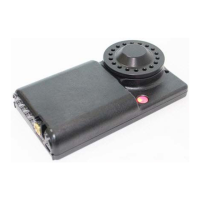
4 Install the flow-measurement adapter in its place in the same way you
would the cyclone inlet cap, threading it in until it becomes tight (you
should see a slight gap between the underside of the flow-measurement
adapter flange and the lip of the UPAS housing.
The UPAS Flow Measurement Adapter is not supplied with the UPAS. It must be
ordered separately from Access Sensor Technologies.