82
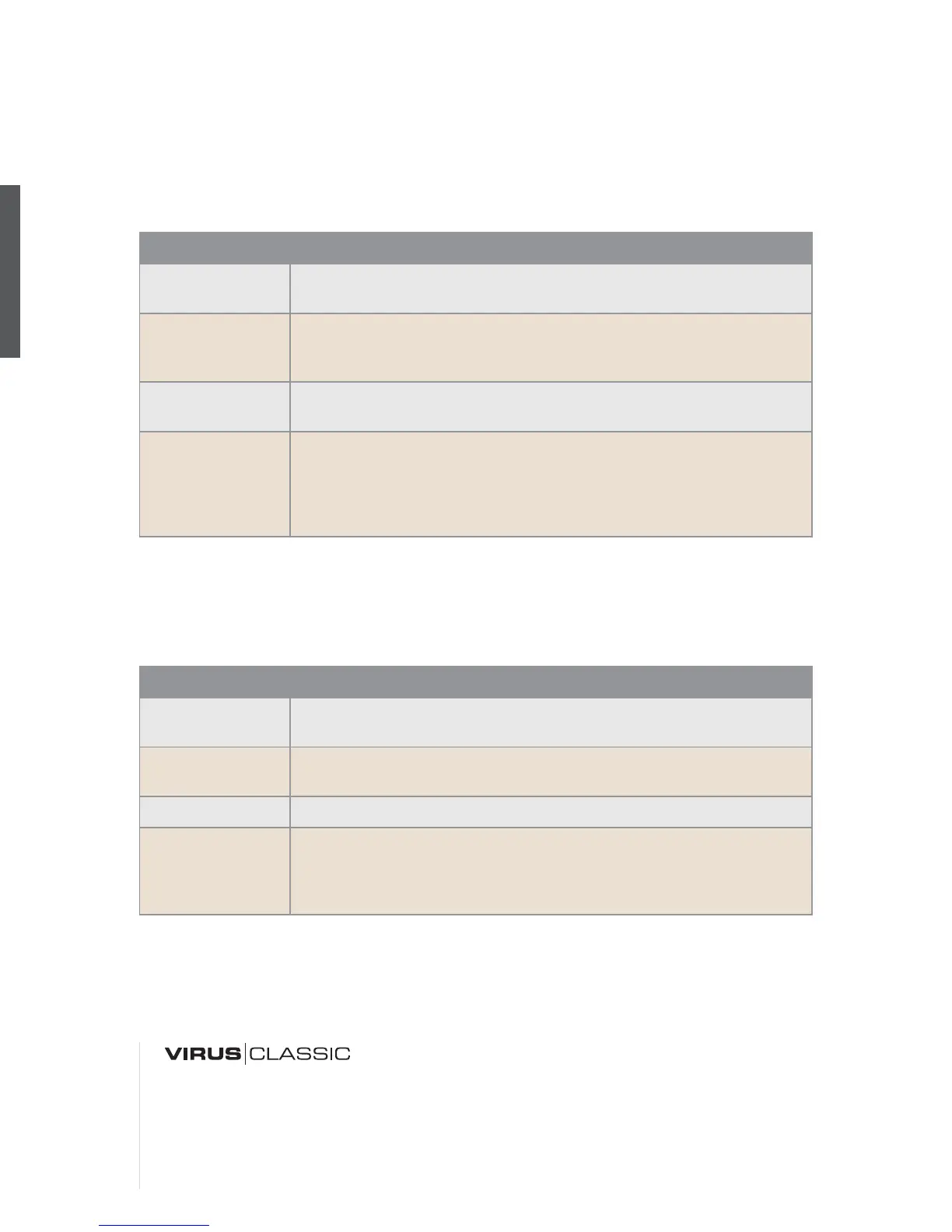
FILT 1 MODE & FILT 2 MODE
FILTER ROUTING
This feature offers four filter routing options which allow you to operate the filters in series or in par-
allel:
Regardless of which FILTER ROUTING option you chose, the SATURATION stage is always post-
Filter-1.
Value Description
LP
The low pass filter suppresses frequencies higher than the CUTOFF fre-
quency (see appropriate section) and allows the lower frequencies through.
HP
The high pass filter works in the opposite manner of the low pass filter: It
suppresses the lower frequencies in a signal and lets the higher frequen-
cies pass.
BP
The band pass filter suppresses both ends of the tonal spectrum and
allows only a narrowly defined bandwidth of the original sound to pass.
BS
The band stop filter, band reject filter or notch filter works in the opposite
manner of the bandpass filter. It allows all of the frequencies of a signal
except for a narrow frequency band around the cutoff to pass. The term
“notch” is fairly descriptive; you might say this filter chops a notch out of
the sound spectrum.
Value Description
SER-4
The filters are switched in series; with two poles each (12dB), both filters
have the same slope for a total of four filter poles (24dB).
SER-6
The filters are switched in series; Filter-1 has four poles (24dB), Filter-2 has
two poles (12dB) so the overall slope is equivalent to six poles (36dB).
PAR-4
The filters are switched in parallel and feature two poles each (12dB).
SPLIT
The filters are switched in parallel and feature two poles each (12dB). Addi-
tionally, they receive independent input signal s (more on this later). The
stereo position of the signals can also be manipulated via the parameter
TWIN MODE PAN SPREAD (see appropriate section) in the EDIT menu.