93
Rev 2.1
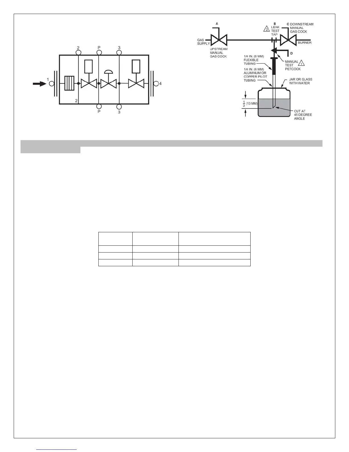
Figure 6.5 Vas Valve Diagram Figure 6.6 Test Setup Diagram
*WARNING- REMOVE POWER FROM THE SYSTEM BEFORE BEGINNING THE VALVE LEAK TEST TO PREVENT
ELECTRICAL SHOCK.
1) De-energize the control system to make sure no power goes to the valves.
2) Close the upstream manual gas cock
3) Make sure the manual test petcock (D) is closed in the leak test tap assembly
4) To test the first Safety shut off valve, remove the 1/8 in. plug from the pressure tap point P.
5) Install the leak test tap into pressure tap point P on the valve body.
6) Open the upstream manual gas cock (A) to re-pressurize the first safety shut off valve.
7) Immerse the 1/4in. tube vertically ½ in. in a jar of water, see figure 6.6.
8) Slowly open the manual test petcock (F).
9) When the rate of bubbles coming through the water stabilizes, count the number of bubbles appearing during a
ten-second period. Each bubble appearing represents a flow rate of .001 cfh. See table below for allowable flow.
Pipe Size
(in. NPT)
Maximum Seat
Leakage (UL)
Maximum Number of
Bubbles in 10 Seconds
1/2 - 3/4 235 cch 6
1 275 cch 7
1-1/4 340 cch 8
Table 6.1 Maximum Bubbles per Pipe Size
10) Close the upstream manual gas cock (A)
11) Remove the leak test tap from the valve body.
12) Using a small amount of pipe sealant on the 1/8 in. NPT plug, reinstall the plug in pressure tap point (P).
13) To test the second safety shut off valve, remove the 1/8" plug from the flange pressure tap point 4.
14) Install the leak test tap into pressure tap point 4.
15) Close the downstream manual gas cock (C).
16) Immerse the ¼ in. tube vertically ½ in. into a jar of water.
17) Slowly open the manual test petcock (D)
18) When the rate of bubbles coming through the water stabilizes, count the number of bubbles appearing during a
ten-second period. Each bubble appearing during a 10 second period represents a flow rate of 0.001 cfh (28 cch).
See table 6.1
19) Remove the leak test tap from the valve body.
20) Using a small amount of pipe sealant on the 1/8 in. plug, reinstall the plug in pressure tap point 4.
21) After completing the test, make sure the downstream manual gas cock (C)
22) Open the upstream manual gas cock (A) and energize the valve through the safety system.
23) Test with rich soap water solution to make sure there is no leak at the test tap (B) or any pipe adapter/valve
mating surfaces.
24) De-energize the valve.
25) Open the downstream manual gas cock (C)
26) Restore the system to normal operation.

 Loading...