39
TC1 Custom Setpoint,
TC2 Custom Setpoint,
TC3 Custom Setpoint,
IGN1 FF Alarm (On when IGN1 is in FF),
IGN2 FF Alarm (On when IGN2 is in FF),
Modbus Control (turns off upon any SD),
TMain1 Mirror,
TMain2 Mirror,
Custom Temperature setpoint for
the selected AUX relay.
-60°C to 1200°C (-76°F to 2192°F)
Deadband value for custom
temperature setpoint for selected
AUX relay
1-5°C or 2-10°F
Note: Both AUX relays will turn off (connecting NC to COM) upon a shutdown or if the system is Off.
Modbus Communications
Modbus/RS-485 Cable Connections – Field Installations
Refer to Appendix C for additional Modbus cabling technical details.
Refer to the document "CSC400_Modbus_Installation_Manual.pdf" for additional details and pictures on additional Modbus
registers, testing, cabling, and troubleshooting.
Cabling
Connect a cable from a PLC (Programmable Logic Controller) or a PC to the 3-pin terminal strip of the CSC400 labeled
"Modbus", observing proper connections:
- The RS-485 standard suggests using twisted pair type cables (CAT5E or a shielded twisted pair with ground) for
connecting devices together. This is definitely a requirement for longer cable runs (25m to 1000m) and for use in
noisy environments like industrial or commercial installations.
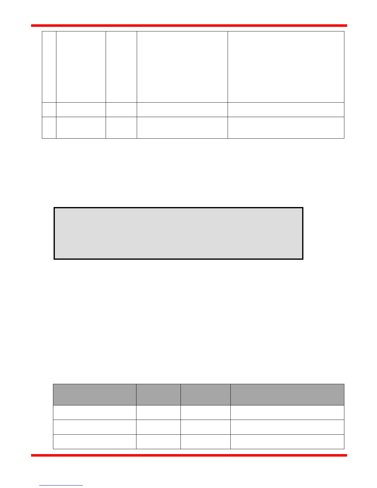
- The RS485 signal naming convention used in this document and by many RS485 transceiver vendors is reversed from
what the EIA/TIA-485 specification states:
Documentation
Naming
Specification
A (“RS485 A +” or "D0 A+")
Non-Inverting, Transceiver Terminal 1, V1
voltage (V1 > V0 for binary 1 (OFF) state
B (“RS485 B –” or "D1 B-")
Inverting, Transceiver Terminal 0, V0
voltage (V0 > V1 for binary 0 (ON) state
GND)
Signal and Optional Power Supply
common ground
Ensure that only industrial-rated equipment is used for field installations, with appropriate
measures for handling noisy environments.
If using a PC with USB-to-RS485 connectivity for field installations, use an industrial-rated
USB hub (preferably one with a metal case) for connecting the PC to the USB-to-RS485 cable.