54
Appendix A - CSC400 Rev 1D Technical Specifications
General Notes:
- All components on the CSC400 Controller are RoHS compliant.
Modbus Notes:
- Receivers are designed to fail-safe to a logic high output state if inputs (terminals A and B) are left un-driven or
shorted. If the bus is un-driven for long periods of time, the receivers are designed to not require line polarization on
the bus (adding a pullup resistor to “A” and a pulldown resistor to “B”). Line polarization may be enabled (via the
two DIP switches on the top of the CSC400 Controller's Modbus DIP switches (4 half-pitch DIP switches)) for use
with other devices on the same RS-485 bus.
- Drivers are protected from excess current flow caused by bus contention or output short-circuits by both an internal
current limit and a thermal-overload shutdown.
- RS-485 inputs (terminals A and B) are protected against ESD (Electrostatic Discharge) events up to +/- 15kV (Air-
Gap and Human Body Model) and up to +/- 8kV Contact Discharge (IEC61000-4-2).
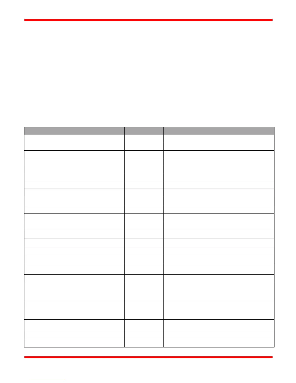
Modbus Slave ID (address)
Modbus/RS-485 Serial Settings:
300, 1200, 2400, 4800, 9600, 19200, 38400
1, 2 (only with parity set to “None”)
-40°C to 60°C ambient
Input voltage on A and B signals
Driver Short Circuit Current Limit
Differential Driver Output, No Load
Differential Driver Output, R
L
1.5 VDC minimum, 2.7 VDC typical, 5 VDC
maximum
Receiver Input Resistance
96k ohms minimum (1/8
th
of a Modbus “Unit Load”)
Receiver Differential Threshold (VA – VB)
-125mV typical
Receiver Input Hysteresis
None or 120ohms (2-pin jumper may be installed by
user)
Line Polarization Resistors
560 ohms +/- 1%, selectable by user via two DIP
switches
Line Polarization Pullup voltage
Line Polarization Pulldown voltage
RS-485 Isolated or Common GND (0V)