60
Appendix D - Troubleshooting
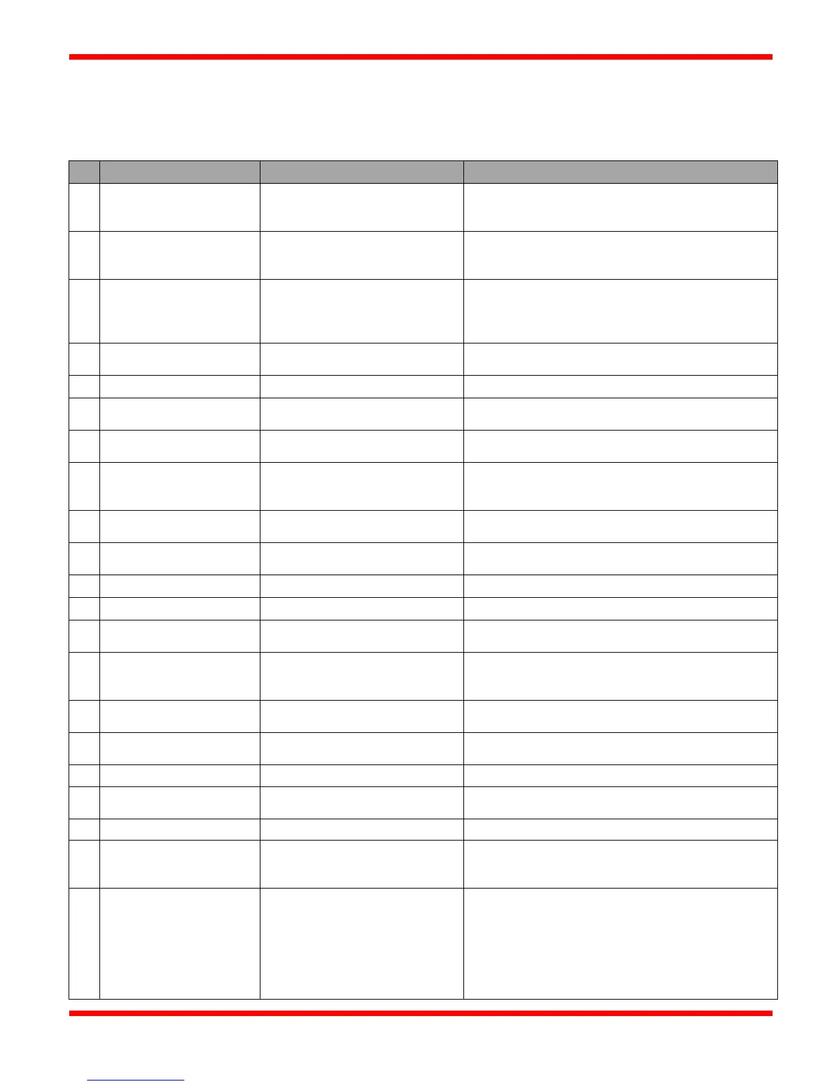
Burner Management Troubleshooting
Fails to attempt ignition
Check if the display is on or not: a menu screen or the
Status screen should always be displayed.
If Display is off, replace fuse with a 6.3A max fuse
Ensure that the minimum input voltage is 11.5VDC
(measured with a volt meter) for use with 2-3
Check all connections on the terminal strips. Ensure
that there are no short circuits, that the wires are
tightly gripped inside the terminals, and that the
screws on each terminal are tight.
POC terminal not closed, display
showing "POC"
Ensure that 12VDC is measured on both the POC+
and POC- terminals
Attempts ignition but
pilot doesn't light
Fuel gas supply to Pilot may be
too high or too low
Pilot fuel gas supply should be set at 5 pounds
Gap setting on ignitor/flame rod
not correct
Gap should be approximately 1/8" (3.175mm) and rod
tip needs to be cut to a sharp point
Ignition cable defective or
insulation worn
Check continuity through the ignition cable.
Multimeter should read close to zero ohms. If not,
cable needs to be replaced.
Ensure that good, thick ground connections are made
at the CSC400 and at the Pilot/burner valve.
Check supplied power to solenoid. Check gas flow
through solenoid.
Clean out Pilot orifice (Do Not redrill!)
Gap setting too wide or rod not
cut to a point
Shorten gap setting to approximately 1/8" (3.175mm)
and recut the ignitor rod tip.
Ignition cable defective or
insulation worn
Check continuity through the ignition cable.
Multimeter should read close to zero ohms. If not,
cable needs to be replaced.
Ensure that good, thick ground connections are made
at the CSC400 and at the ignitor tip.
Contaminated ignitor rod or Pilot
nozzle
Remove Pilot assembly, clean rod and nozzle, and
reinstall.
Solenoid valve not
opening
No power to solenoid valve or
faulty solenoid valve
Replace defective solenoid valve
then closes again
Driver setting for the attached
Verify that the Low Power Solenoid Driver DIP
switch settings are matched to the solenoid valves
Some larger solenoid valves rated for 12VDC require
an output voltage very near to 12VDC. Measure the
output voltage on the solenoid terminals to ensure that
it's sufficient (approx. >= 11.5VDC).
Higher current drawn on each solenoid output will
cause slightly higher voltage drops which may
interfere with solenoid operation. Input voltage may