51
4-20mA Input Connection Notes for Rev 1D CSC400 Boards
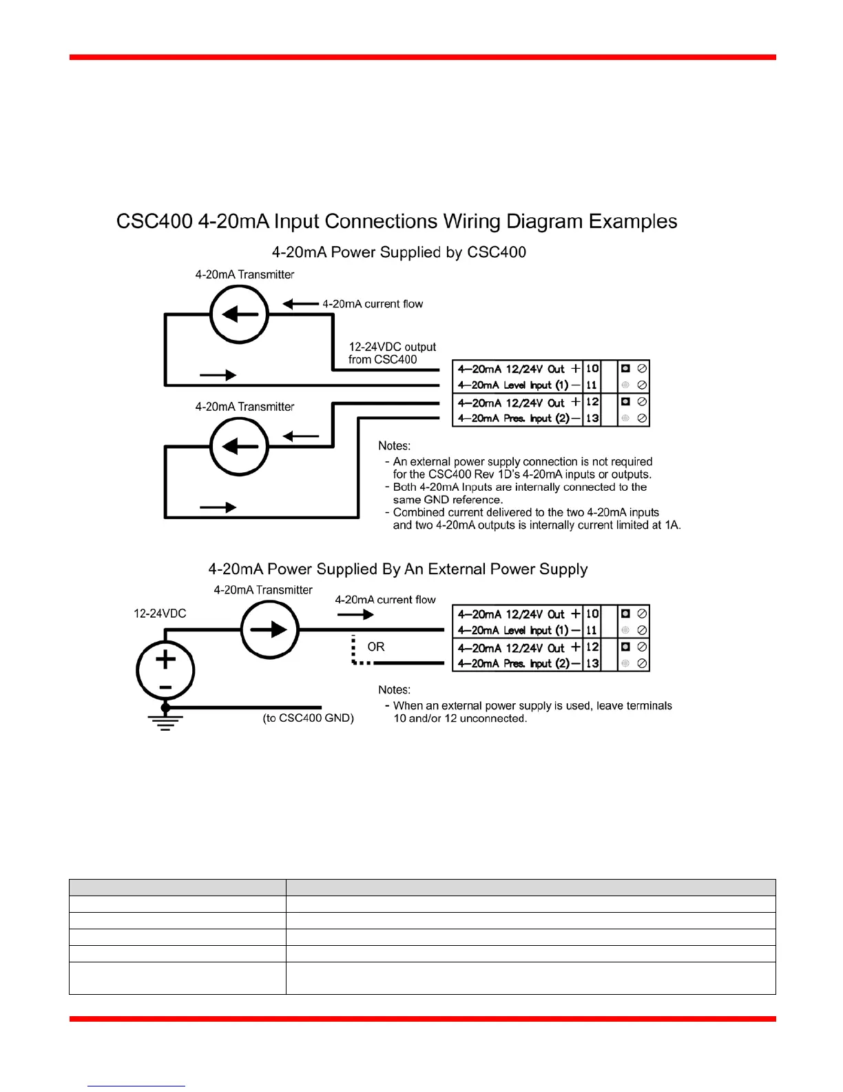
The CSC400 Rev 1D board changes how the 4-20mA inputs and outputs are powered. The CSC400 Rev 1D board provides a
shared 12-24VDC power switch with a combined maximum output current of 1A for all 4-20mA Inputs and Outputs. The
provided input voltage (eg: 12VDC or 24VDC) will be the same voltage on the power output terminals for the 4-20mA Inputs
(terminals 10 and 12) and the same voltage supplied to the two sets of 4-20mA Output circuitry.
Figure 13 - CSC400 4-20mA Input Connections Wiring Diagram Examples
4-20mA Input DIP Switches
There are 4 DIP switches for each 4-20mA Input. They select the inline (series) resistor added to each 12/24V Output
(terminals 10 and 12). A DIP switch is "On" when it is moved to the right side (towards the "Local Mount of the Ignition
Module" area). The inline resistance options are present to assist with 4-20mA Input impedance adjustments and for possible
HART communication devices. DIP Switches labeled "1:" correspond to "Level Input (1)". DIP Switches labeled "2:"
correspond to "Pressure Input (2)". Operation of each 4-20mA Input is identical regardless of the "Level" or "Pressure" label.
Number of DIP Switches On
Resulting Inline Series Resistance
1 of top three DIP switches "On"
2 of top three DIP switches "On"
3 of top three DIP switches "On"
0 ohms: All external resistors are bypassed, shorting the internal 12/24V power
supply output to the terminal(s) (10 and 12) directly