57
The common ground connection should use a wire from an unused pair in the CAT5E cable.
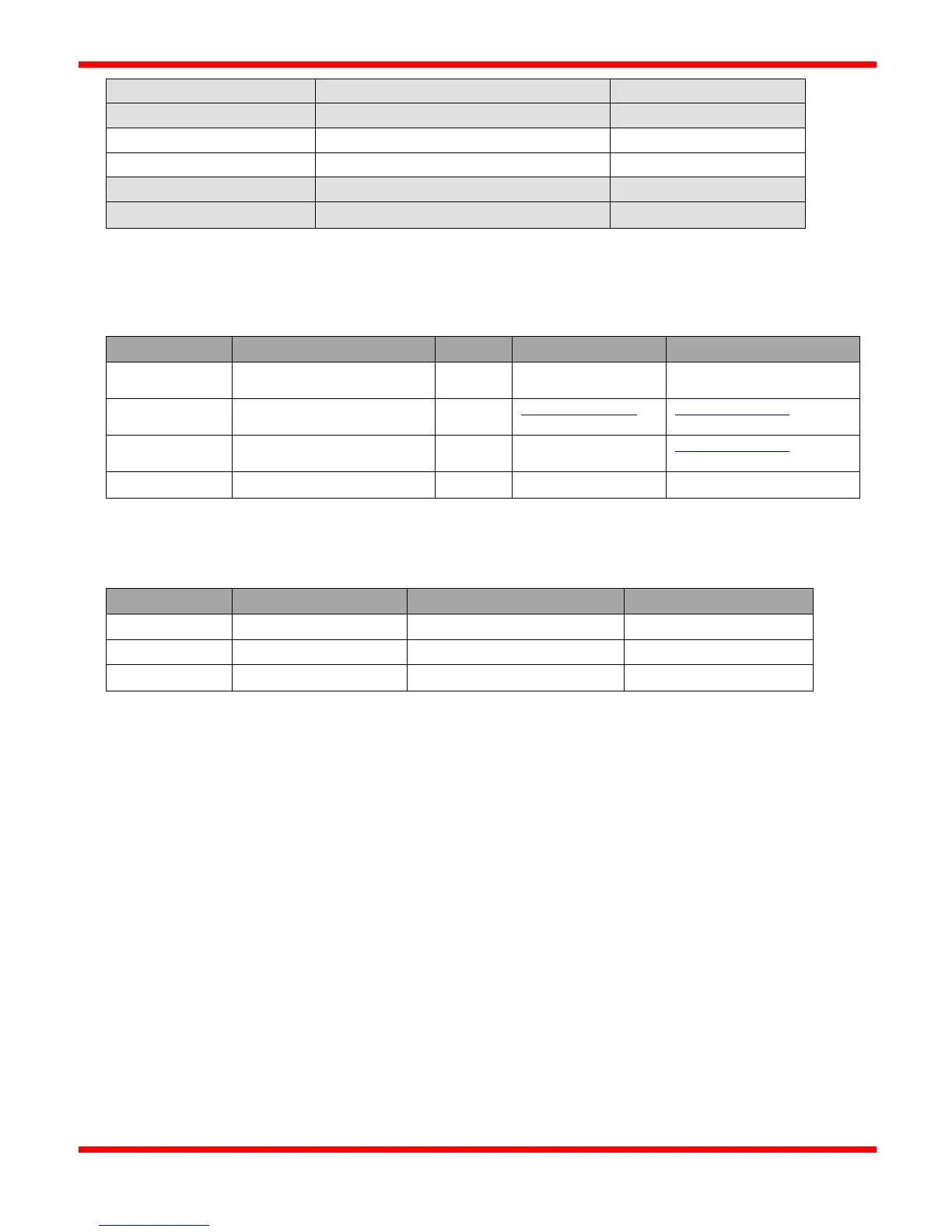
Examples of USB to RS485 cables
UPort 1150/1150I
www.digikey.com,
www.mouser.com
www.mouser.com
Industrial-Rated USB Hubs
Wiring topology
For connecting multiple Modbus devices on to the same RS-485 bus, a “daisy-chain” wiring topology should be used (one long
cable with short “stub” connections to each device). Ensure that short “stub” connections are made at each device to the main
RS485 cable to reduce signal reflections and interference.
A “star” or “ring” wiring topology should not be used. An example of a “star” configuration would be separate, multiple
cables branching out from the Master to each individual slave device. Only one cable should be connected at the Master end.
Line Polarization
Line Polarization enables a pullup resistor on the “Data A +” signal and a pulldown resistor on the “Data B –“ signal. It
ensures that the bus is put into a known state with the “Data A +” signal High and the “Data B -” signal Low. Some RS485
receivers are susceptible to external noise or interference if the RS485 bus is not driven to a known state when the bus is idle
(no device is driving a signal on the bus).
Line Polarization should only be enabled on one device on the RS485 bus, if necessary. Usually this is done at the end of the
bus where the master device resides. The CSC400 Controller allows the implementation of Line Polarization via two DIP
switches located on the top of the board.