56
Appendix B - Modbus/RS-485 Cabling Technical Details
Additional Modbus documentation is available at
www.modbus.org:
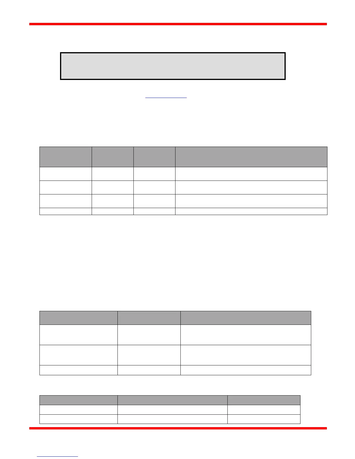
RS-485 Signal Naming Conventions
The RS485 signal naming convention used in this document and by many RS485 transceiver vendors is reversed from what the
EIA/TIA-485 specification states:
Modbus/RS485
Naming
Specification
Non-Inverting, Transceiver Terminal 1, V1 voltage (V1 > V0
for binary 1 (OFF) state
Inverting, Transceiver Terminal 0, V0 voltage (V0 > V1 for
binary 0 (ON) state
common GND)
Signal and Optional Power Supply common ground
Half-Duplex vs Full-Duplex
Half-duplex communication allows only one device to communicate over the two RS-485 wires (one differential pair) at a
time. Full-duplex communication adds another pair of wires to allow bi-directional communication between a PC/PLC master
and a slave unit simultaneously.
The CSC400 provides a three pin terminal for half-duplex communication between the CSC400 and a host master Modbus
device.
Cable Types
Cable Type To Use For
Testing
RS485 cable should have stripped wires for
connecting to terminal blocks on the CSC400
Controller (eg: SCADAPack,
Use a matched twisted pair for RS485A+/B-
Eg: Blue for RS485A+
Blue with white stripe for RS485B-
Allowable Pairings of CAT5E Cable
CAT5E Cable Wire Color Twisted Pairs
Refer to the document "CSC400_Modbus_Installation_Manual.pdf" for additional details
on additional Modbus registers, programming, testing, and troubleshooting.