52
4-20mA Output Connection Notes for Rev 1D CSC400 boards
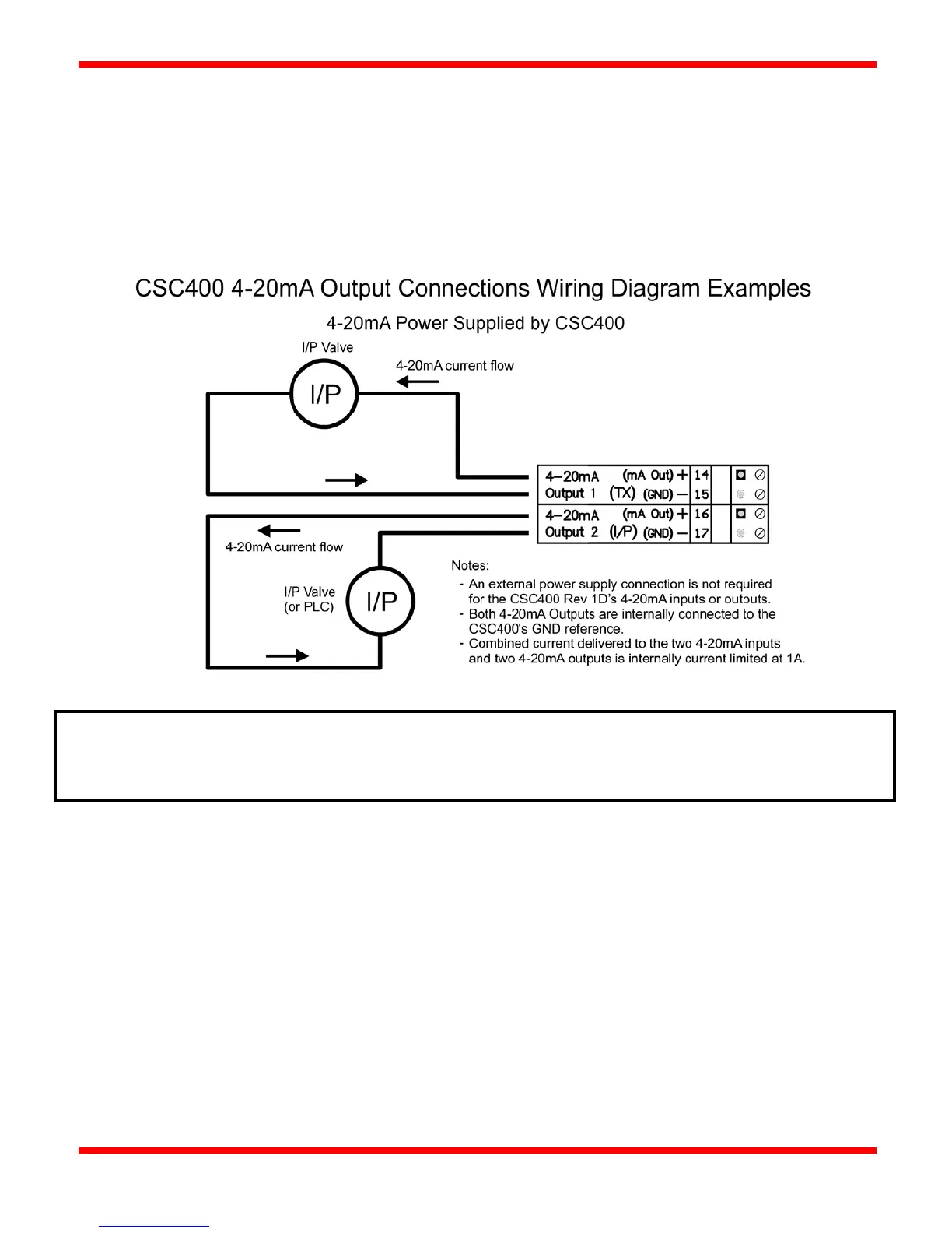
The CSC400 Rev 1D board changes how the 4-20mA inputs and outputs are powered. The CSC400 Rev 1D board provides a
shared 12-24VDC power switch with a combined maximum output current of 1A for all 4-20mA Inputs and Outputs. The
provided input voltage (eg: 12VDC or 24VDC) will be the same voltage on the power output terminals for the 4-20mA Inputs
(terminals 10 and 12) and the same voltage supplied to the two sets of 4-20mA Output circuitry. The 4-20mA Output terminals
14 and 16 should be connected directly to the external I/P valve, 4-20mA PLC input, or other 4-20mA controlled device.
Figure 14 - CSC400 4-20mA Output Connections Wiring Diagram Examples
Notes:
- An output of 3.5mA or 22mA means there's an error. This could mean that the selected
thermocouple for the 4-20mA Output is disabled or not connected.