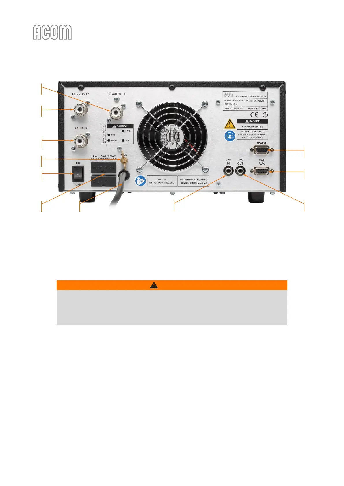
Figure 2-3 | Rear panel - Connections
Figure 2-3 | Rear panel - Connections
a) GND stud
First, connect the wing-nut grounding stud of the amplifier (on the rear panel, marked GND) to the station's
grounding system (see Figure 2-3 | Rear panel - Connections, Pos. (a)).
WARNING
Note that the grounding system may have to withstand currents over 15 A with
insignificant voltage drop on it. Therefore, it may be necessary to improve it considerably,
i.e., to become less resistive, with heavier leads and lower-resistive ground path. The
grounding leads should be at least 4 mm² (AWG 11 or SWG 13).
For details and recommendations on the grounding and RF counterpoise system concerning the
electromagnetic compatibility see also Section 3.6.f) Elimination of electromagnetic compatibility (EMC)
problems.
b) KEY IN connector
This is the amplifier's input for receive/transmit control from the transceiver.
The transceiver switches the amplifier from receive mode into transmit mode (RX/TX) by grounding of the
KEY IN input.
Run a shielded cable from the "ground on transmit" connector or terminal on your transceiver to the
amplifier rear panel KEY IN connector (see Figure 2-3 | Rear panel - Connections, Pos. (b)). The KEY IN connector
uses a standard RCA phono plug.