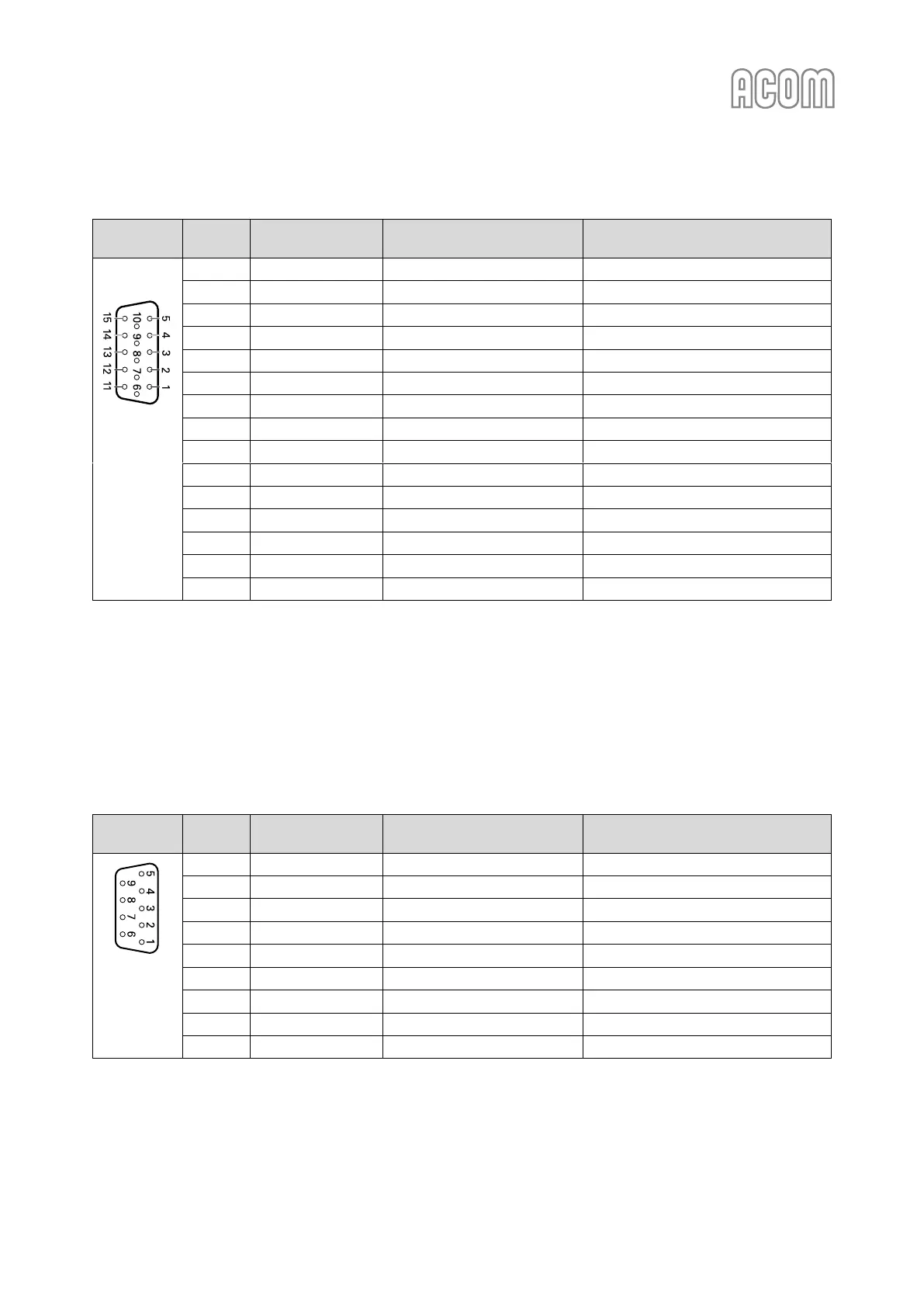
Table 2-1 | Signals and pin out of the CAT/AUX connector
b) RS-232 interface connector
Please, see Figure 2-3 | Rear panel - Connections, Pos. (4).
This connector may remain unused until you decide to control the amplifier remotely.
Please, see Section 6 REMOTE CONTROL.
Table 2-2 | Signals and pin out of the RS-232 connector