1-151-15
1-151-15
1-15
Chaosdr 1 Mnshdranarc CdrbrhoshnnChaosdr 1 Mnshdranarc Cdrbrhoshnn
Chaosdr 1 Mnshdranarc CdrbrhoshnnChaosdr 1 Mnshdranarc Cdrbrhoshnn
Chaosdr 1 Mnshdranarc Cdrbrhoshnn
Hard Drive LED Connector (HDLED)
This connector supplies power to the cabinet IDE activity LED.
Read and write activity by devices connected to the Primary or
Secondary IDE connectors will cause the LED to light up.
Reset Switch Lead (RST)
The connector can be connected to a momentary SPST type
switch that is normally open. When the switch is closed,the
motherboard resets and runs the POST.
1.7.8 CMOS Function Selection: JP6
A battery be used to retain the mainboard configuration in
CMOS RAM.
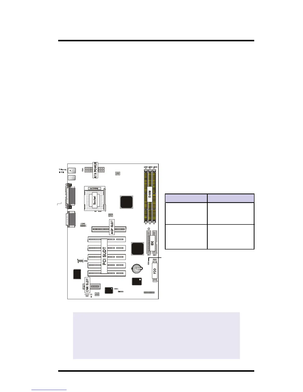
USB1
COM1
6A815EP1
not onboard
VGA
AGP1
Speaker out
Line in
MIC in
Printer
IR
FAN1
JP6
FAN3
GAME1
Intel
Intel
PCI SLOT2
PCI SLOT1
PCI SLOT3
PCI SLOT4
PCI SLOT5
CNR SLOT
J7
1
FAN2
JP4
BIOS
I/O CHIP
LAN C HIP
JP7
LED1
VGA
Optional
JP6
Pin Definition
1-2 Normal
(Default)
2-3 Clear CMOS
NOTE:
(Please follow the procedure below to clear CMOS data.)
(1)Remove the AC power line. (2)JP6(2-3)Closed.
(3)Wait five seconds. (4)JP6(1-2) Closed.
(5)AC Power on.
(6)Reset your desired password or clear CMOS data.