Table of Contents
ii
Introduction
1. Motherboard Description
1.1 Introduction 1-1
1.2 Package Contents 1-1
1.3 Features 1-2
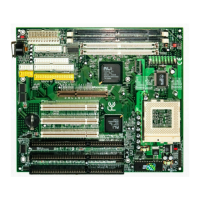
1.4 6A815E1 & 6A815EP1 Motherboard Layout 1-5
1.5 CPU Installation 1-7
1.6 SDRAM Installation 1-8
1.7 Connectors & Jumper Setting
1.7.1 Back Panel Connectors
1.7.1.1 PS/2 Mouse/Keyboard CONN. 1-9
1.7.1.2 USB Connector: USB1 1-10
1.7.1.3 Serial Interface ports 1-10
1.7.1.4 Parallel Interface port 1-10
1.7.1.5 VGA Interface port 1-11
1.7.1.6 Joystick / Midi Connector 1-11
1.7.1.7 Audio Port Connector 1-11
1.7.2 ATX 20-pin Power Connector: ATX 1-11
1.7.3 Floppy Disk Connector: FDD1 1-12
1.7.4 Hard Disk Connectors: IDE1/IDE2 1-12
1.7.5 CPU Fan Connectors: FAN1/2/3 1-12
1.7.6 CD-Audio-IN Connector: CN1 1-13
1.7.7 Front Panel Connector: J7 1-14
1.7.8 CMOS Function Setting: JP6 1-15
1.7.9 BIOS Flash(JP4) 1-16
1.7.10 Keyboard wake up Setting: JP7 1-16
1.7.11 IrDA Connector: IR 1-17
1.7.12 Front two USB Connector: USB2 1-17
1.7.13 STR LED: LED1 1-17
1.7.14 CNR Card Setting: J8 1-17