Revision: 1.23
30
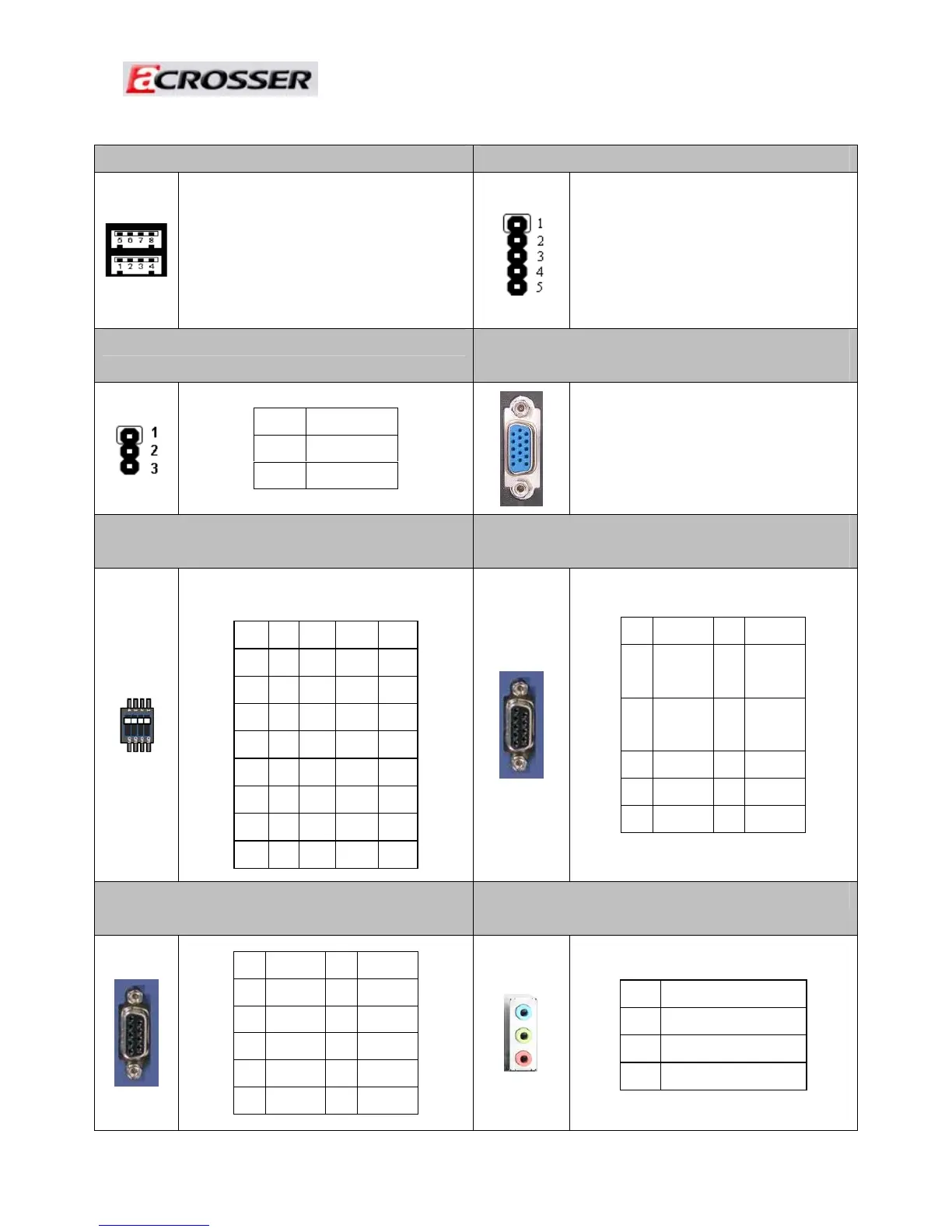
17. CN7: USB connector 18. CN28: PIC Programming connector.
Upper: Port #4.
Lower: Port #3.
PIC programming connector.
19. CN20: Setting Voltage level of Battery 20. VGA1: D-SUB-15 female connector for
VGA output
STATUS SETTING
1-2
+24V
2-3
+12V (Default).
D-SUB-15 female connector for
VGA output
21. SW1: DIP switch for power mode select
(2.3)
22. COM1&COM2 : D-SUB-9P Male connector
× 2 (2.7)
Mode 1 2 3 4
0 ON ON ON ON
1 ON ON ON OFF
2 ON ON OFF ON
3 ON ON OFF OFF
4 ON OFF ON ON
5 ON OFF ON OFF
6 ON OFF OFF ON
7 ON OFF OFF OFF
PIN DEFINE PIN DEFINE
1
DCD
/DT-
2
SIN
/DT+
3
SOUT
/422R+
4
DTR
/422R-
5
GND
6
DSR
7
RTS
8
CTS
9
RI_12V
23. COM3&COM4: D-SUB-9P Male connector
x 2
24. AUDIO1: AUDIO connector
PIN DEFINE PIN DEFINE
1
DCD
2
SIN
3
SOUT
4
DTR
5
GND
6
DSR
7
RTS
8
CTS
9
RI_12V
Color SIGNAL
Blue
Remote Switch
(2.4)
Green Line Out
Pink MIC IN