TECHNICAL CHARACTERISTICS
CHIMNEY CONNECTION CHARACTERISTICS
It is mandatory to ventilate the boiler room. The high or low air vent opening dimensions
depend on the appliance power and the boiler room size. Refer to the local regulations in force.
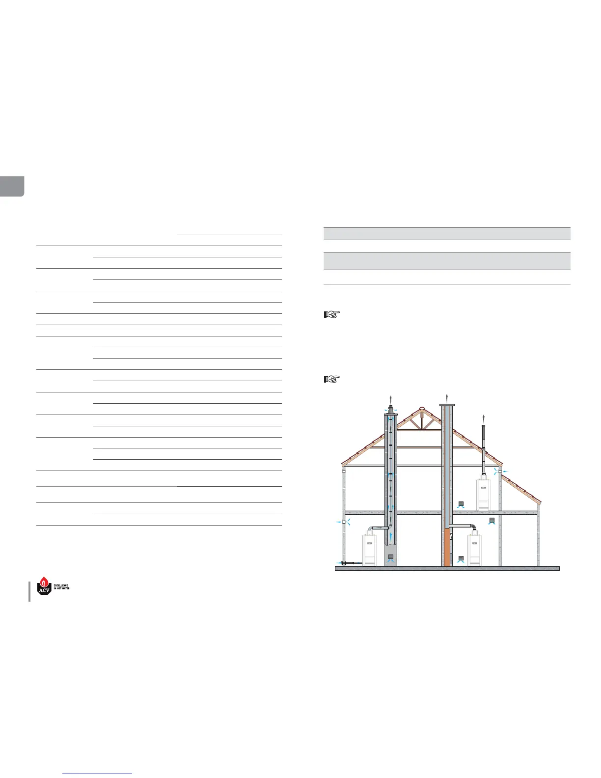
FLUE PIPE CONNECTION TYPES
It is mandatory to use ACV flue systems to connect the appliance.
B23 : Connection to an exhaust duct that discharges the combustion products outside the room
where it is installed, with the combustion air being drawn directly from the boiler room.
B23P: : Connection to a combustion product exhaust system designed to operate with positive pressure.
C53(x) : Connection to separate ducts for supplying combustion air and discharging combustion prod-
ucts; these ducts may end in zones with dierent pressure levels, but are not allowed to be
installed on opposite walls of the building.
Main Characteristics
HM201
Air/flue pipe Ø Parallel mm 250
Max. allowed ue pipe pressure
drop
Pa 130
Max recommended length (corresponding
length in meters of straight pipes)
12 m
Available connection types
B23 - B23P - C53(x)
C
53(x)
B
23
B
23P
COMBUSTION CHARACTERISTICS
Main Characteristics
HM201
G20/G25
Input (PCI)
max kW 220.0
min kW 58.4
Output at 100%
(80/60°C) kW 198.0
(50/30°C) kW —
Eciency at 100%
(80/60°C) % 91.0
(50/30°C) % —
Eciency at 30% load (EN677) % 94.0
Combustion eciency at 100% % 91.5
NOx (Class 5)
Max. output mg/kWh 68.0
Min. output mg/kWh 45.0
Weighted mg/kWh 43.0
CO
Max. output ppm 4
Min. output ppm 2
CO
2
Max. output %CO
2
9.5
Min. output %CO
2
8.9
Max gas ow rate
G20/G25
20 mbar m³/h 25.4
25 mbar m³/h 29.5
Temp of ue gases
Average
°C
150
Max.
°C
194
Min.
°C
92
Average temp. of combus-
tion products
DHW mode °C 187
Mass ow rate* of ue
gases
Nominal g/s 113
Standby loss
∆T = 45 K
W 678
∆T = 30 K
W 408
* Mass flow rate values were calculated for G20 with an air factor of 1.3.
 Loading...