pressure to 0 bar.
• Water flowing out of the drain valve may be extremely hot and could cause severe
scalding. Keep people away from the hot water discharge.
Set-up conditions
• Boiler switched o using the ON/OFF
master switch
• External power supply isolated
• Fuel/gas supply closed
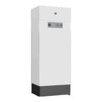
Heating circuit draining procedure
1. Close the isolating valves (1).
2. Connect the drain valve (2) to the sewer
with a hose.
3. Open the drain valve (2) to empty the
heating circuit of the boiler.
4. Close the drain valve (2) once the heating
circuit of the boiler is empty.
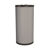
DHW circuit draining procedure
Before draining the DHW tank,
make sure that the heating
(primary) circuit pressure is null.
1. Open fully a draw-off tap (3) for
about 60 minutes to make sure that
the DHW tank has cooled down.
2. Close the isolating valves (1).
3. Connect the drain valve (2) to the
sewer with a hose.
4. Open the drain valve (2) and drain
the DHW tank water to the sewer.
5. Open the draw-off tap (3) to
accelerate the draining process.
If it is located lower than the tank
connection, open a draw-off tap
located higher in the system.
6. Close the drain valve (2) and the
draw-off tap (3) once the DHW
tank of the boiler is empty.
Cold water
Hot water
1
1
2
1
2
3
3
1
2
4
3
5
1
6
2
He atMas ter2 01: A1004320 - 664Y7500 • A
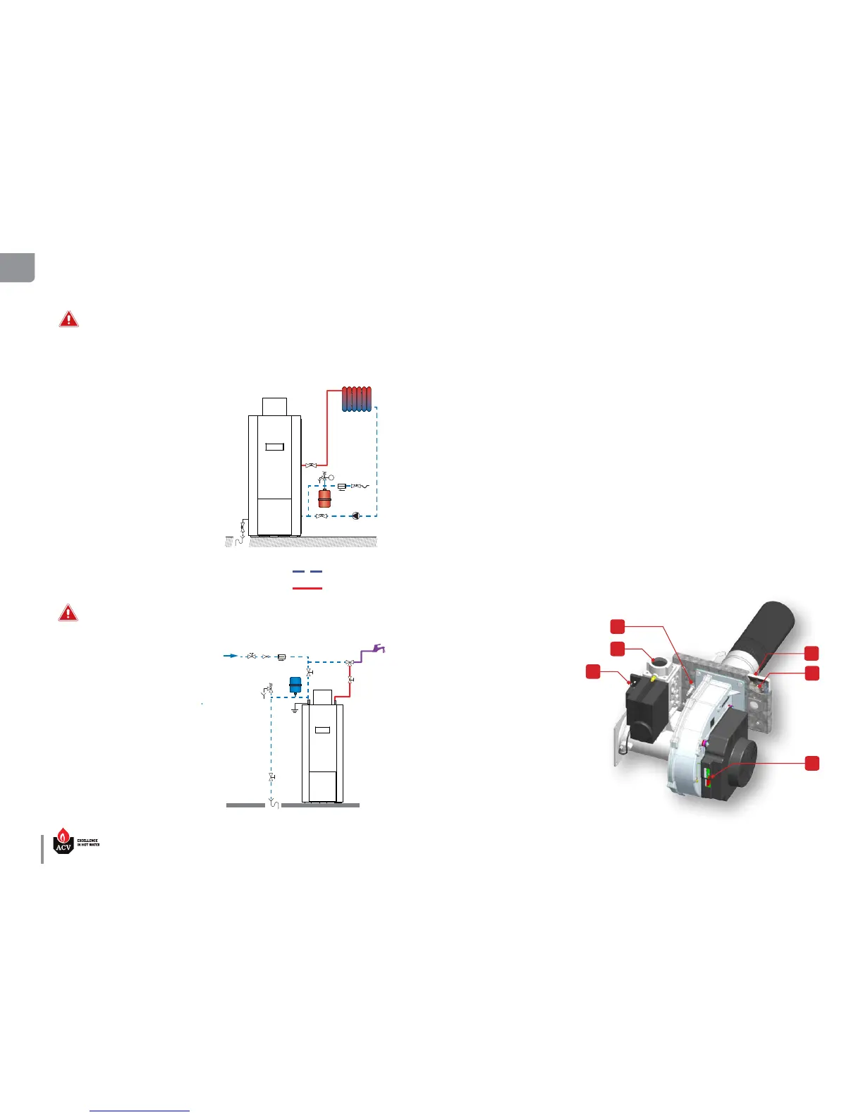
REMOVAL AND INSTALLATION OF THE BURNER
Set-up conditions
• Appliance shut down
• External power supply isolated
• Gas supply closed
• Front panel and burner cover removed (refer to “Removal and Installation of the Front Panel and the
burner cover” on page 29).
Removal procedure
1. Disconnect all plugs from the gas valve (6), the electrode (2), and the fan assembly (5).
2. Release the gas connection (1).
3. Using a socket wrench, release the four burner hood attaching hex. screws (4) and retain them for
reinstallation.
4. Pull the burner assembly out of the combustion chamber.
5. Check visually the burner insulation plate (3) condition. Replace if cracked or damaged.
6. Remove, check and reinstall the electrode, refer to “Removal, Check and Installation of the Burner
Electrode” on page 35, as required.
Installation procedure
1. Reinstall the burner assembly into the combustion chamber, using four retained hex. screws (4).
2. Reconnect all disconnected plugs, to the gas valve (6), the electrode (2), and the fan assembly (5),
refer to the Burner Installation Manual provided with the burner for connection details.
3. Reconnect the gas connection (1).
Follow-on tasks
1. Restart boiler, refer to “Re-
starting after Maintenance” on
page 35
DRAINING THE APPLIANCE