STARTING UP THE APPLIANCE
Set-up conditions
• All connections made
• Electrical power supply on
• Gas supply open
• Hydraulic circuit(s) full of water
Procedure
1. Check that there is no gas leak.
2. Push in the ON/OFF master switch (
).
3. If a room thermostat is installed, possibly increase the temperature set point to generate a demand.
4. Check the gas pressure and allow the appliance to heat up for a few minutes
5. Check and adjust the burner according to local standards and regulations, refer to “Checking and
Adjusting the Burner” on page 32.
6. Set the central heating temperature to the required value using the control panel. Refer to “Setup
Guide” on page 7 and to the Installer’s Handbook.
7. After 5 minutes of operation, bleed the heating circuit until all air is evacuated and restore a 1.5 bar
pressure.
8. Bleed the central heating circuit once again and top it up with water to get the required pressure
if necessary.
9. Make sure that the central heating system is properly balanced and, if needed, adjust the valves to
prevent certain circuits or radiators from getting a ow rate that is far above or below the set rate.
Follow-on tasks
1. Close the heating circuit lling valve and disconnect the lling connection as required.
2. Check that there are no leaks.
3. Check that the ow rate in the appliance is sucient as follows :
• Operate the appliance at maximum power
• Once the temperatures are stable, read out the supply and return temperatures
• Check that the dierence between the supply and return temperature is equal to or less than 20k.
• If the Delta T is higher than 20k, check the pump settings/specications.
CHECKING AND ADJUSTING THE BURNER
When the burner operates at full power, the CO
2
rate must be within the limits mentioned in
the technical characteristics, (see “Combustion characteristics” on page 18).
Set-up conditions
• Operating appliance
Procedure
1. Check if the ACVMAX parameters are set to meet the user's requirements (refer to “Setup Guide” on
page 7), and change them if required.
2. Put the appliance to maximum power mode (Refer to the Installer’s Handbook).
3. Using a pressure tester, check that the dynamic gas pressure at the gas valve is at least 18 mbar.
4. Allow the appliance to heat for a few minutes until it reaches at least 60°C.
5. Measure the burner combustion by placing the flue gas analyzer probe in the measurement unit
port on the flue pipe and compare the CO and CO
2
values displayed with those indicated in the
combustion characteristics table.
6. If the CO
2
value differs by more than 0.3%, carry out the adjustment mentioned in the procedure
below.
7. Then put the appliance to the minimum power mode (Refer to the Installer's Handbook provided
with the appliance). Allow the appliance to stabilize for a few minutes.
8. Measure the CO
2
level. It must be equal to the value at full power, or lower than that value by 0.5%
maximum. If there is a significant deviation, please contact ACV's support department.
CO
2
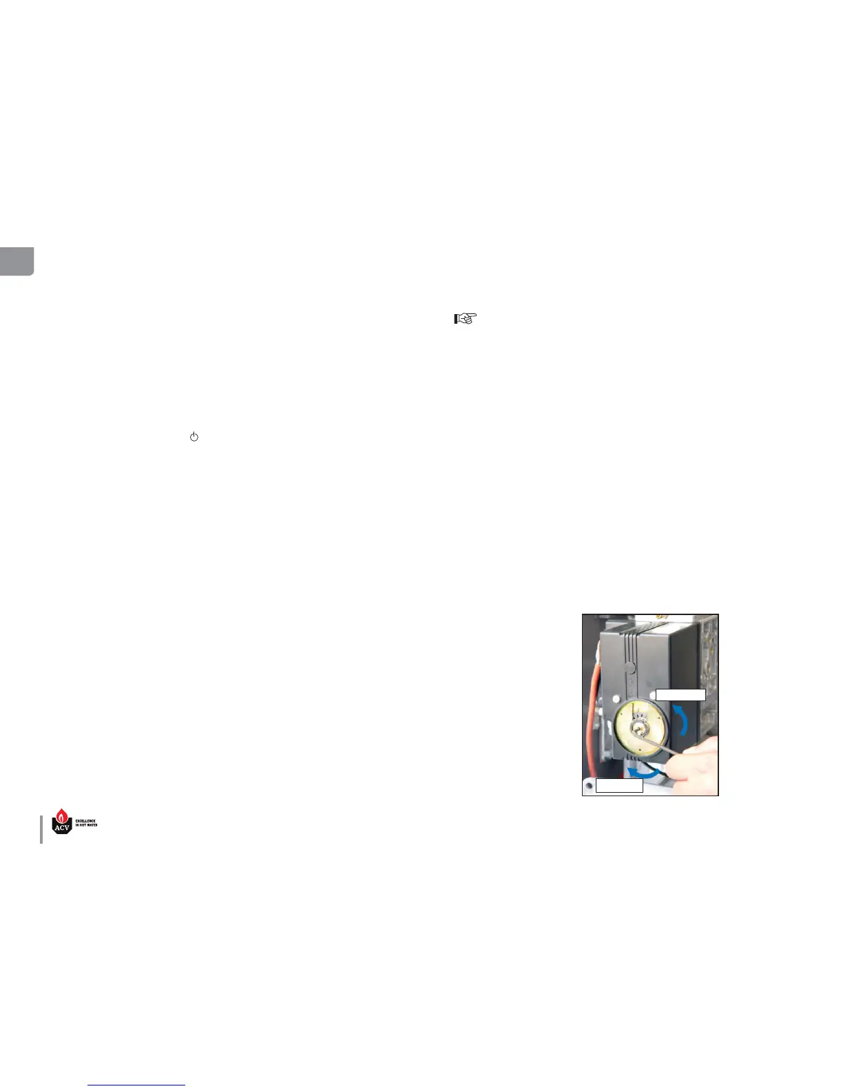
adjustment procedure
To adjust the CO
2
rate, rotate the throttle screw (1) :
• to the left (counterclockwise) to increase the CO
2.
rate.
• to the right (clockwise) to decrease the CO
2.
rate.
Follow-on tasks
None
Increase
Decrease