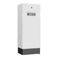
ELECTRICAL CHARACTERISTICS HEATMASTER
®
201
230 VAC OUTPUT !
HM 201
Main Characteristics
Rated voltage V~ 230
Rated frequency Hz 50
Electrical consumption
Max. W 525
Min. W 210
Electrical consumption at
30% load
W 240
Electrical consumption in
standby
W 5
Rated current (Fuse) A 10
Class IP 40
Key
1. ON/OFF master switch
2. Gas valve
3. Burner power supply
4. Ground
5. Burner PWM plug
6. NTC2 return sensor
7. NTC1 supply sensor
8. NTC - Low temperature circuit
For low temp circuit operation, black wires from X3, terminals 1 & 6 must be
routed to X20, terminals 3 & 4.
9. High limit switch
10. Low water pressure sensor
11. PCB (Display)
12. ACVMax programmation plug
13. A & B Modbus (option)
14. NTC3 DHW sensor
15. NTC4 outdoor temperature sensor (option)
16. Room thermostat 1 (option)
17. 0-10 Volt (option)
18. Room thermostat 2 (option)
19. Ignition and ionization cable
20. Connection for Interface Control Unit (option)
21. 5AT slow-blow fuse (3x) for internal and optional circuits*
22. Terminal block :
• Line
• Pump
• DHW
• Alarm
• CH
• Flame
• Pump
* 5AT slow-blow fuse (2x) for internal circuits and connection of CH, DHW and Flame output + 5AT slow-blow fuse (1x) for connection of
Alarm, P3 and P4 (connector P14).
2 spare 5AT slow-blow fuses are located on the back side of the electrical box, for fuse replacement, if required.