EasyManua.ls Logo

ACV HeatMaster 201 - Configuration and System Set-Up; Basic High-Temperature Heating Configuration

ACV HeatMaster 201
40 pages
Print Icon
To Next Page IconTo Next Page
To Previous Page IconTo Previous Page
Loading...
He atMas ter2 01: A1004320 - 664Y7500 • A
en
30
EN
FR
NL
ES
IT
DE
PL
RU
CONFIGURATION AND SYSTEM SETUP
BLOCK DIAGRAM
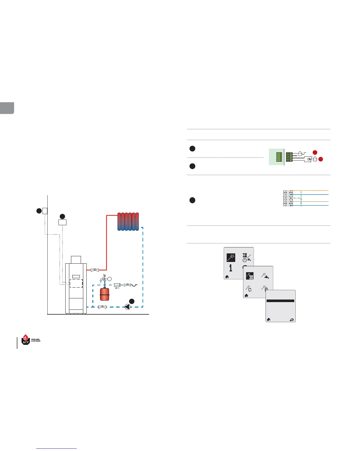
The heating system (radiators) is controlled by an On/O room thermostat.
The domestic hot water tank is controlled by an intermediate NTC sensor (optional). The domestic hot
water priority is always active.
In this conguration, the appliance constantly adapts its operation to the outdoor temperature if an out-
door temperature sensor is connected.
The heating pump is triggered as soon as the room thermostat generates a heat demand.
BASIC CONFIGURATION  HEATMASTER 201 : HIGH TEMPERATURE
HEATING CIRCUIT WITH CONTROL BY ROOM THERMOSTAT AND
OPTIONAL OUTDOOR SENSOR.
* The illustrations are for information only. For more details on the required accessories, refer to the latest ACV price list.
ITEM DESCRIPTION QTY ELECT. TERMINALS TO CONNECT TO**
1
Room thermostat 1
X6 3
&4
ACV Max
1
2
3
4
5
6
7
8
9
10
11
12
13
14
15
16
17
18
19
20
21
123456
1 2 3 4 5 6
W
W
W
W
W
W
4 5 6
1 2 3
X15
1 2 3 4 5 6 7 8 9 10
Y
Y
Y
Y
Y
Y
Y
Y
Y
Y
X11
6 7 8 9 10
1 2 3 4 5
3 4
1 2
X16
1 2 3 4 5 6 7 8 9 10 11 12 13 14
W
R
Or
Or
Bk
Bk
Bk
8 9 10 11 12
1 2 3 4 5
13
6
14
7
X2
1 2 3 4 5 6 7 8 9 10
W
R
Y
R
Y
BK
BK
W
6 7 8 9 10
1 2 3 4 5
X3
1 2 3 4 5 6 7 8 9 10 11 12
V
W
R
Bk
7 8 9 10 11
1 2 3 4 5
12
6
X1
X12
X9
P14
123
4
123
456
B
Br
B
Br
P13
X10 0
B
Or
123
Bk
B
Y/Gr
Y/Gr
Y/Gr
Y/Gr
Y/Gr
Y/Gr
Y/Gr
Y/Gr
V
Br
B
Br
Br
Y/Gr
B
B
3
F00
N
L
L
V
ON / OFF
1
Br
Br
Br
Br
Br
Br
Br
B
B
B
B
B
B
B
B
Y/Gr
Br
B
Y/Gr
Br
B
Br
Br
Y/Gr
B
13
15
14
16
17
18
2
X10
12
16
20
Line
Pump
DHW
Alarm
CH
Flame
Pump
230 V
123
1
2
1234
123456
X7
X4
X6
X5
Bus A
Bus - Ground
Bus B
0-10 Volt - Ground
0-10 Volt - Input
NTC 3
NTC 4
1
2
19
X18
B
Br
B
Br
B
Br
21
22
5AT Fuse
5AT Fuse
5AT Fuse
X6 1&2
2
Outdoor temperature sensor,
12kΩ
1
3
Circulator pump 1
1
2
3
4
5
6
7
8
9
10
11
12
13
14
15
16
17
18
19
20
21
X10 0
Y/Gr
Y/Gr
Y/Gr
Y/Gr
Y/Gr
Y/Gr
Y/Gr
Y/Gr
3
N
L
L
ON / OFF
1
Br
Br
Br
Br
Br
Br
Br
B
B
B
B
B
B
B
B
Y/Gr
Br
B
Y/Gr
Br
B
Br
Br
Y/Gr
B
2
Line
Pump
DHW
Alarm
CH
Flame
Pump
230 V
22
X100 13 to 15
By-pass kit :
To read the ow rate more eas-
ily. To be installed in the HT or
LT circuit, as required.
1 --
EZ Setup
Heating EZ Setup
Select CH Demand
Thermostat & Outd. Curve
Constant & Outdoor Curve
Constant & Setpoint
0 - 10 V Modulation Signal
1
2
3
ACVMax

Table of Contents

Other manuals for ACV HeatMaster 201

Related product manuals