RESTARTING AFTER MAINTENANCE
Set-up conditions
• All removed components reinstalled
• All connections made
• Power supply
• Gas supply open
• Hydraulic circuit(s) full of water
Procedure
1. Make sure there is no gas leak at the gas connections.
2. Switch the appliance on using the ON/OFF master switch.
3. Set the appliance at maximum power and check the absence of gas leaks.
4. Check the gas pressure and CO
2
adjustment in accordance with “Checking and Adjusting the Burner”
on page 32.
Follow-on tasks
None
REMOVAL, CHECK AND INSTALLATION OF THE BURNER ELECTRODE
Set-up conditions
• Burner removed (refer to “Removal and Installation of the Burner” on page 34).
Removal procedure
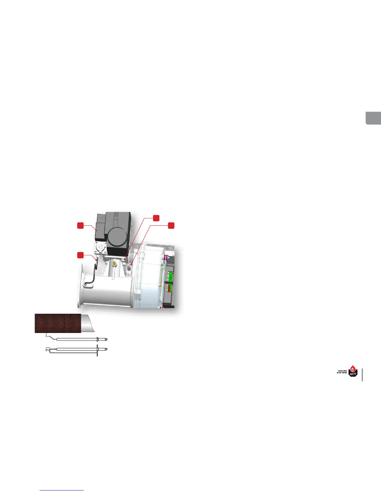
1. Disconnect the hose (1) from the gas valve (2).
2. Remove 4 socket head screws (3) from the bottom of the gas valve (2). Retain the screws for rein-
stallation.
3. Remove two screws (4) from the electrode. Retain the screws for reinstallation.
Check and installation procedure
1. Check the condition and correct distance between electrode tips, according to illustration below.
Replace electrode if required.
2. Install the electrode in the
provided location, with a
new gasket and the 2 re-
tained screws (4).
3. Check the correct position
and distances of the elec-
trode, according to the il-
lustration below. Adjust as
required.
4. Install the gas valve (2) on its
support using the 4 retained
screws (3).
5. Connect the hose (1) to the
gas valve (2).
Follow-on tasks
• Reinstall the burner. Refer to
“Removal and Installation of
the Burner” on page 34.