APPLIANCE DESCRIPTION
CONFIGURATION IN A SYSTEM
The boiler can be set up in dierent types of systems, either high or low temperature, or both, with or
without external Domestic Hot Water tank. It is up to the installer to determine the best solution and
reach the results the user is expecting.
A basic conguration is shown in this manual for HeatMaster 201 (see “Conguration and system set-up”
on page 30), with the required accessories, required electrical connections and ACVMax set up using
the EZ setup function.
Additional congurations requiring a more advanced setup are shown in the Installer’s Handbook, avail-
able on the ACV website (www.ACV.com). The setup of those systems must be made exclusively by the
installer using the installer code.
For any other conguration that is not mentioned in either manual, please contact your ACV represent-
ative.
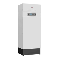
HEATM ASTER® 201
The HeatMaster® 201 boiler is equipped with ACV's "Tank-in-Tank" concept, as well as high eciency
charging pumps and with an ACV air/gas premix burner BG-2000 M with low NOx emissions. During op-
eration, the burner starts automatically as soon as the appliance temperature gets lower than the preset
temperature and stops as soon as the preset temperature is reached.
The HeatMaster® 201 features a built-in frost protection mechanism: as soon as the ow temperature
[NTC1 probe] drops below 7°C, the central heating pumps are activated. As soon as the ow temperature
is at 5°C, the burner starts up until the ow temperature rises above 15°C. The pumps continue to run for
around 10 minutes. The function can be enabled or disabled through the installer menu. When the frost
protection is disabled, only the pumps operate.
An anti-freeze function is also available if an outdoor temperature sensor is connected, the pumps are
activated when the outside temperature drops below the threshold dened through the Freeze protec-
tion function in the installer menu. In order to enable the appliance to protect the whole system against
freezing, all the valves of the radiators and the convectors should be completely open.
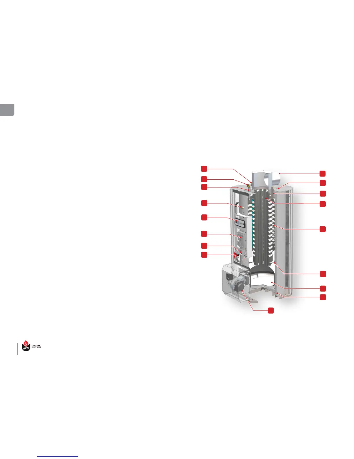
HEATMASTER® 201 OVERVIEW
1. Chimney reduction with horizontal outlet Ø
250 mm
2. DHW tank dry-well + NTC3 sensor
3. DHW hot water outlet
4. Flue gas tubes and turbulators
5. Stainless steel hot water production tank
6. Primary circuit tank
7. Combustion chamber
8. Foam insulation
9. Air/gas premix burner
10. Circulator pump (2x - only one shown)
11. Pressure sensor
12. Electrical panel (with spare fuses at the back)
13. ACVMax Control panel
14. Pressure gauge (primary circuit)
15. Cconnection for recirculation (DHW)
16. Automatic air vent
17. Cold water inlet + dip tube