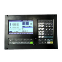
NCT-04/03/02 Punch CNC System (Commissioning Manual)
2.4.1.6 Mechanical Punching Crank Switch Position Indication (double brake for example)
This is a mechanical punching running diagram, stopping top dead center and feeding zone
are schematic only, and the range of feeding prohibited area is smaller than shown. The position
of the brake pad depends on the clearance of the clutch and pressure.
Pay special attention that: the top dead center position is unique; when the punch is at the
highest point, the top dead center sensing block aligns with the top dead center switch.
2.4.1.7 Punch Signal Installation Diagram and Corresponding Punch Control Timing

 Loading...