NCT-04/03/02 Punch CNC System (Commissioning Manual)
Relocation clamp forward distance P1.098
3.6.3 Test Code
Refer to "Programming Manual" 7. Relocation instructions for details
3.7 Punching Status Display Interface
3.7.1 Interface Introduction
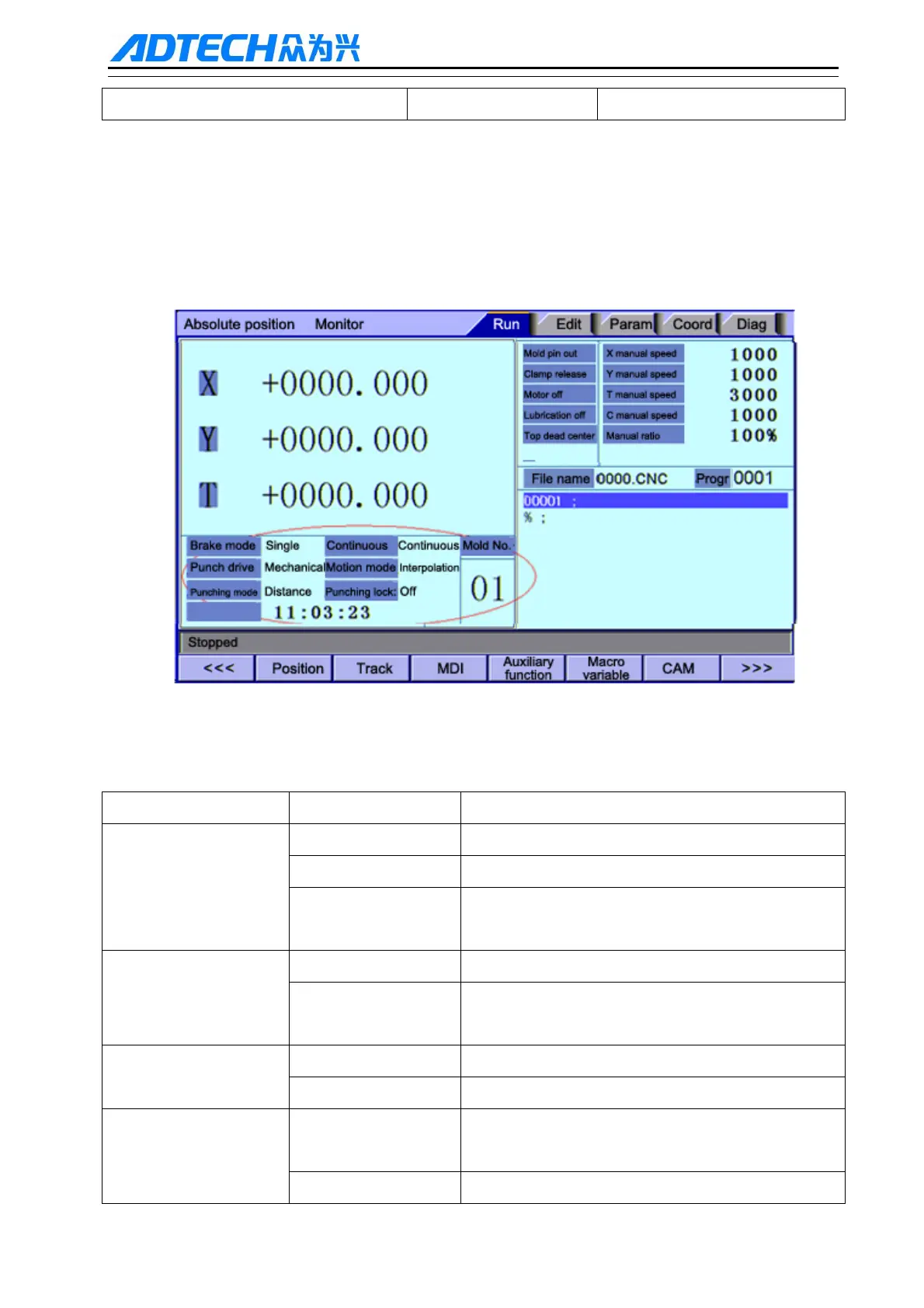
The following Fig. 3 - 1 shows the punch status display interface:
Fig. 3-1
Table 3 - 1 is the punch state description:
Table 3-1
Function Parameter Introduction
Brake mode Feeding Feeding signal as the off clutch signal
Single stop Single stopping top dead center as off clutch signal
Double stop Single / continuous punching off clutch is controlled
by a separate switch signal
Single/Continuous Single The system will pause after punching a hole
Continuous Punching process does not stop until the end of the
program
Punch drive Mechanical The punch main drive is mechanical
Hydraulic The punch main drive is mechanical flywheel
Running mode Point The starting speed, acceleration and rapid traverse
speed can be set for each feeding axis individually.
Interpolation Feeding axes arrive simultaneously