be caused due to the influence of the distributed capacitance, thus damaging the
motor insulation or produce large leakage current to trigger inverter over current
protection. When the length of the motor cable is longer than 100 meters, AC output
reactor shall be installed.
e) Grounding terminal
:
The terminal must be grounded reliably, and the resistance of the ground wire must
be less than 0.1Ω. Otherwise, fault may be caused, or the inverter may be damaged.
Do not share the grounding terminal
and terminal N of zero line of the power
supply.
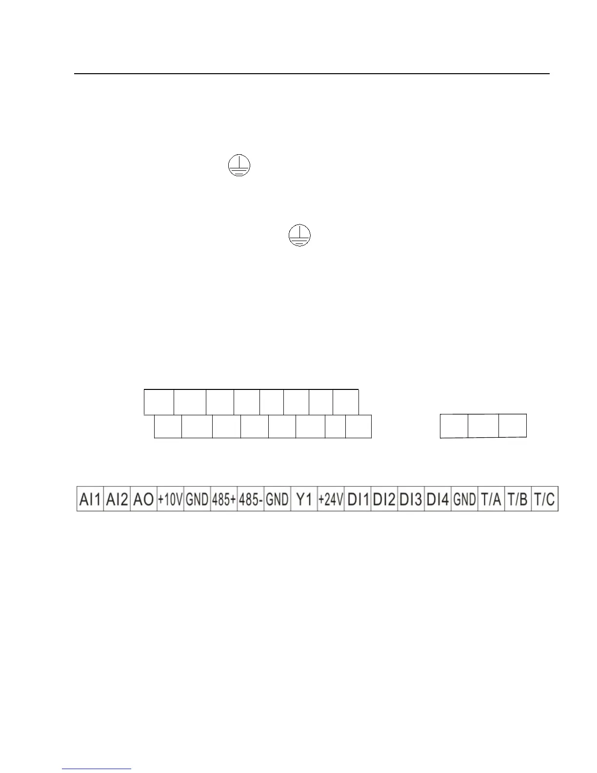
3.2.5 Control Terminals and Wiring
3.2.5.1 The terminals of the control circuit are arranged as shown in the
following diagram:
Fig.3-5 Terminal Layout of the Control Circuit
3.2.5.2 Function Description of Control Terminal
Tab.3-3 Function Description of C220/C420 Inverter Control Terminal
 Loading...