3.2.4.2 Description of main circuit terminals of three-phase inverter:
Terminals Name Description
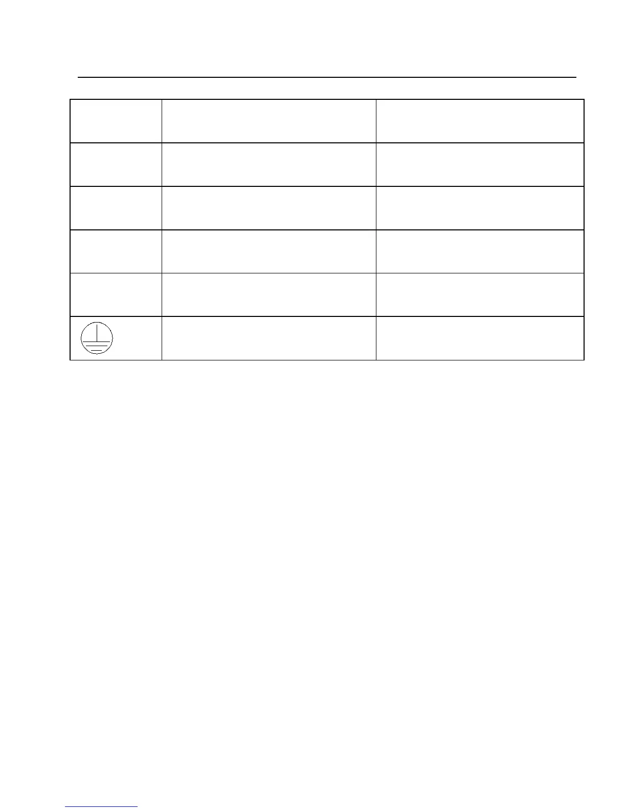
R、S、T
Three-phase power input
terminal
Connect to the AC three-phase
380V power supply
(+)、(-)
Negative and positive
terminals of DC bus
Shared DC bus input point
(+)、PB
Connecting terminal for
brake resistor.
Connection points for the brake
U、V、W
Output terminal of inverter Connect to three-phase motor
Grounding terminal Grounding terminal
3.2.4.3 Wiring Precautions
a) Input power supply terminals L, N, R, S or T:
There is no sequence requirement for the wiring at the Input side of the inverter.
b) DC bus (+) and (-) terminals:
The DC bus (+) and (-) terminals still have residual voltage at the time of power-off.
Do not touch the equipment until the charge LED is OFF and the voltage measured
with multi meter is less than 36V.
The wire length of the brake unit shall not be longer than 10 meters. Twisted wires
or pair wires shall be used and connected in parallel.
Do not connect the braking resistor directly to the DC bus, otherwise, the inverter
may be damaged, and fire may be caused.
c) Connecting terminals (+) and PB of brake resistor:
The recommended wiring distance for the brake resistor shall be less than
5m.Otherwise, the inverter may be damaged.
d) Inverter output sides U, V and W:
The inverter output side cannot connect to the capacitor or surge absorber, otherwise,
the frequent inverter protection may be caused, or the inverter may be damaged.
If the wire between the motor and the inverter is too long, electrical resonance may
 Loading...