EasyManua.ls Logo

Advanced Control C220 Series - Page 43

Default Icon
225 pages
Print Icon
To Next Page IconTo Next Page
To Previous Page IconTo Previous Page
Loading...
Mechanical and Electrical Installation
C220/C420 Mechanical and Electrical Installation
42
Potentiometer
10V
AI1
GND
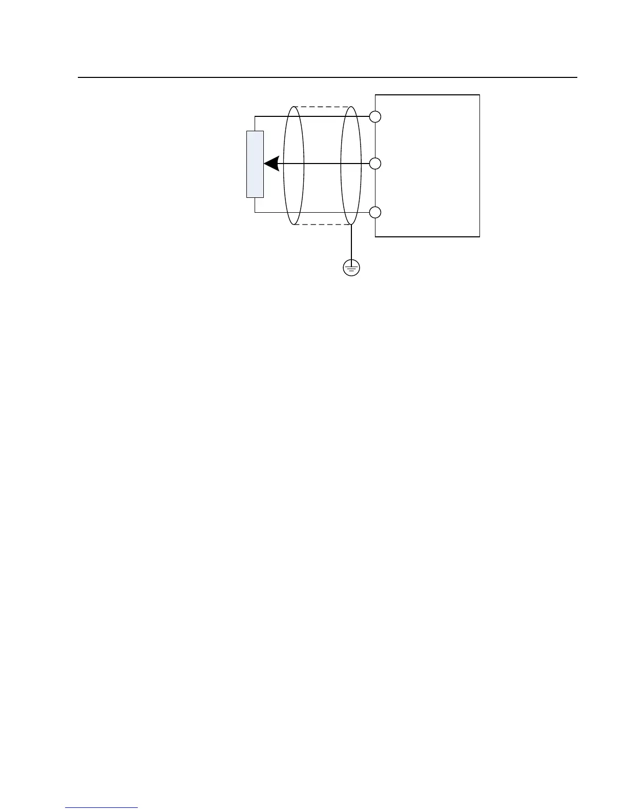
Fig.3-6 Schematic Diagram for Connection of Input Terminal of Analog Signal
B. Digital input terminal:
It needs to employ shielded cable generally, with cable length of no more than 20
meters.
When active driving is adopted, necessary filtering measures shall be taken to
prevent the
interference to the power supply.
It is recommended to use the contact control mode.

Table of Contents