EasyManua.ls Logo

Advanced Control C220 Series - Page 44

Default Icon
225 pages
Print Icon
To Next Page IconTo Next Page
To Previous Page IconTo Previous Page
Loading...
Mechanical and Electrical Installation
C220/C420 Mechanical and Electrical Installation
43
DI1(Default FWD)
DI3
DI4
COM
24V
DI2(Default REV)
DI terminal connection Mode 1Default):
CN1 in the NPN mode and use an internal power
supply
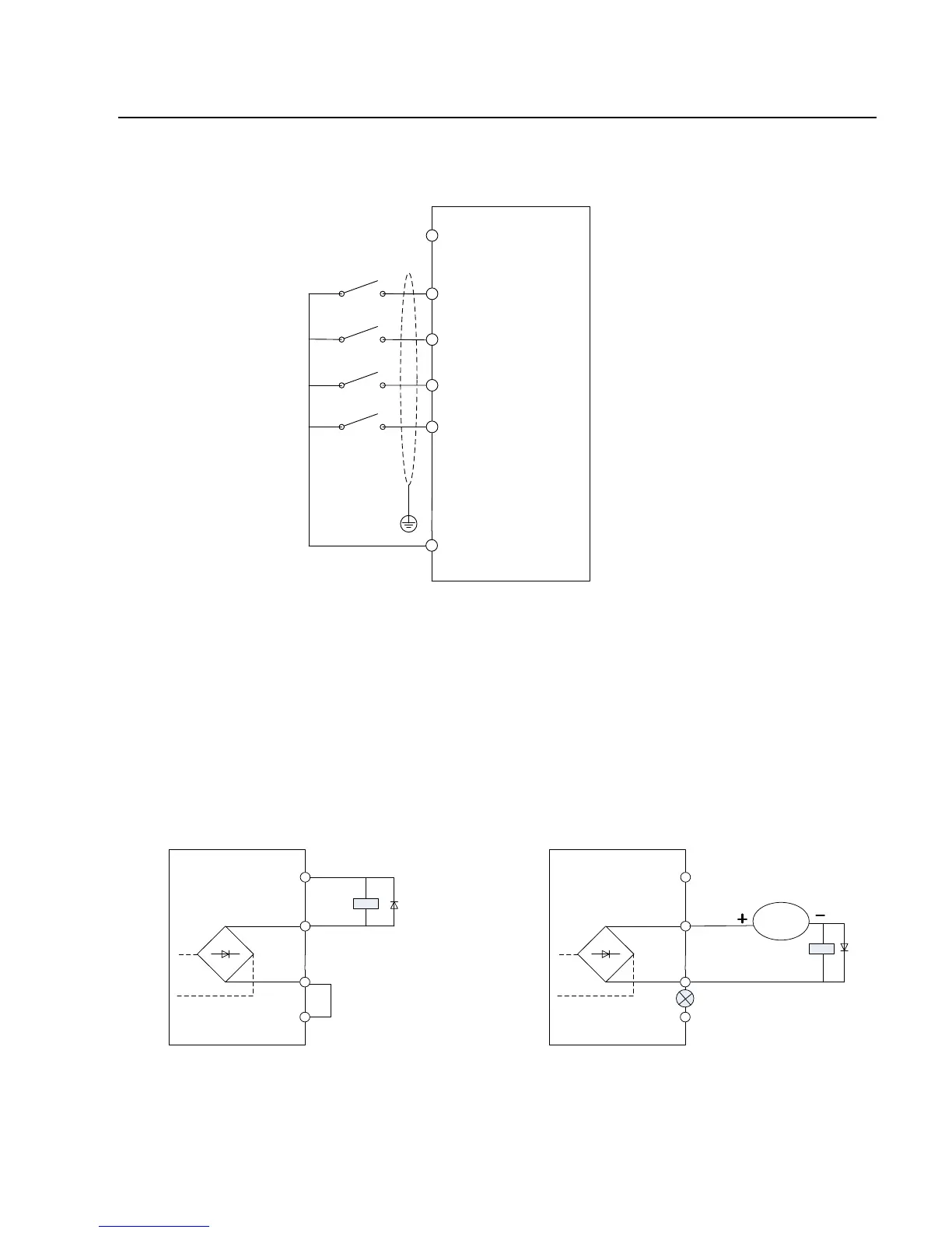
Fig 3-7 Digital input terminal wiring diagram
C. Digital output terminal:
When the digital output terminal needs the drive relay, absorption diode shall be
installed at the two sides of the relay coil. Otherwise it may damage DC 24 power
supply easily.
Caution: The absorption diode shall be installed with correct polarity, as shown in
Fig.3-8. Otherwise, when there the digital output terminal has output, the DC 24V
power supply and output circuit will be damaged immediately.
Y1
CME
24V
COM
Relay
Internal Power Supply
Y1
CME
24V
COM
DC9-
30V
Diode
External Power Supply
Relay
Diode
Fig.3-8 Schematic diagram for connection of digital output terminal

Table of Contents