78
Advanced
™
Osmometer Model 3250 User’s Guide
1. Slide the tool squarely up onto the mandrel, round end first, with
the stir/freeze wire located as shown in Figure 8.
2. Bend the metal probe stem gently by hand, as necessary, to align
the probe along the RAISED V CENTERLINE of the probe alignment
tool.
3. With the alignment tool squarely up on the mandrel, the bottom
of the probe should rest on the main level, as shown in Figure 8.
If vertical adjustment is necessary, first loosen the probe setscrew.
Then raise or lower the probe within its mandrel as necessary, and
then retighten the probe setscrew gently (overtightening will crack
or distort the thin plastic wall of the mandrel). Recheck the probe
position.
4. The bottom of the stir/freeze wire should be even with the small
step, as shown in Figure . As necessary, remove the head cover,
loosen the stir/freeze wire setscrew(s) and reset the stir/freeze wire.
Retighten the stir/freeze wire setscrew(s). Then bend the wire, if
necessary, so that the lower portion is parallel to the sample probe
and spaced about .04 inches (1 mm) away from the sample probe.
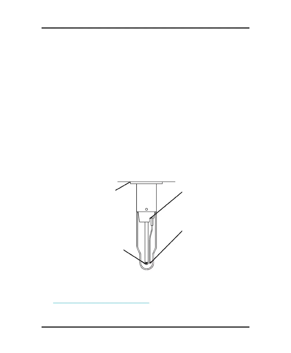
The flange of the mandrel must
be flush with the head chassis.
The black bead in the probe tip must
be in the center of a 0.2-mL sample
in the sample tube, at equal distances
from all nearby surfaces. It must be
the same distance from the bottom of
the tube as it is from the side walls.
The stir/freeze wire should be
about the width of the stir/
freeze wire away from the
mandrel where it exits from
the mandrel.
The tip of the stir/freeze wire
should be about the width of
the stir/freeze wire away from
the probe. Bend the wire if
necessary. The tip of the stir/
freeze wire should be even with
the top of the black thermistor
bead inside the glass probe
tip. Loosen the stir/freeze wire
setscrews to enable vertical
adjustment. Re-tighten the
setscrews gently to avoid
cracking the thin side wall of
the mandrel.
Figure 9: Mandrel, Probe and Stir/Freeze Wire Adjustment
5. After any probe or stir/freeze wire position adjustment, check and
adjust the stir/freeze amplitude, as necessary, as recommended in
Stir/freeze amplitude adjustment.
6. After making any probe and/or stir/freeze wire adjustments, check
the instrument calibration and recalibrate as necessary.
 Loading...


