30
Advanced
™
Osmometer Model 3250 User’s Guide
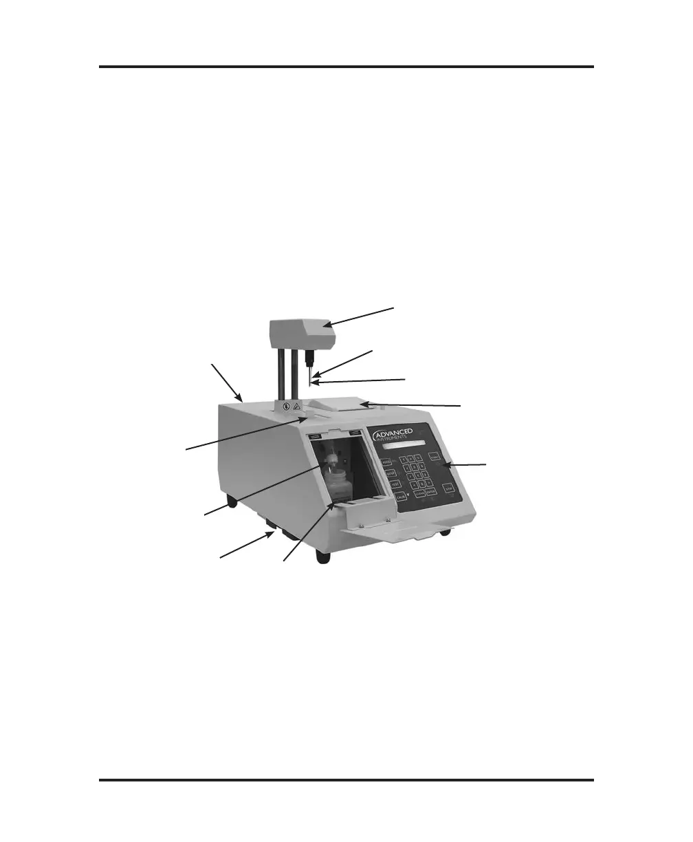
Function of major components
Operation of the instrument will be quicker and easier if you become
familiar with the locations and functions of the components, systems
and controls described below before proceeding further.
Operating head (Figure 3, Item 1)
The operating head contains a stir/freeze wire with electrical means to
vibrate it; an ultra-stable, ultra-precise thermistor sample probe; and
devices to automatically locate the probe and sample in the freezing
chamber.
Supervisor/Operator
Keyswitch, Power Switch,
Fuse Holder, Barcode,
and RS-232 Connector on
Back Panel (see Figure 5)
Freezing
Chamber (8)
Air Filter (7)
Heat Transfer
Fluid Filter (5)
Replace Heat
Transfer Fluid
Filter Line (6)
Operating Head (1)
Stir/Freeze Wire (2)
Sample Probe (3)
Display Panel
and Keypad (4)
Printer (9)
Figure 3: Model 3250 Components and Controls
Freezing chamber (Figure 3, Item 8)
Sample cooling is performed by a thermoelectric cold stage. The
chamber contains a small amount of heat transfer fluid for optimum
cooling capacity.