UNO-2484G_V2 User Manual 8
2.1 Introduction
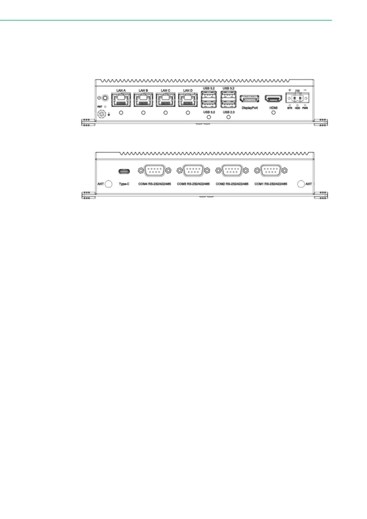
The following diagram demonstrates the location of UNO-2484G V2’s motherboard
and extension kit’s internal/external connectors.
Figure 2.1 Front Panel of UNO-2484G V2
Figure 2.2 Rear Panel of UNO-2484G V2
2.2 Serial Communication Ports
The UNO-2484G V2 is equipped with four standard COM serial communication ports
– COM1, COM2, COM3, and COM4. The port settings can be adjusted from the
BIOS menu. Drivers are installed automatically during OS installation.
2.2.1 COM Port Interfaces (COM1, COM2, COM3, COM4)
The UNO-2484G V2 features four RS-232/422/485 ports (DB9, 50 ~ 115.2 kbps).
The default setting for COM1 ~ 4 is RS-232. These settings can be adjusted in the
BIOS menu. (Please refer to User Manual- Appendix A.10 for RS232/422/485 set-
tings).
2.2.2 Power Connector
UNO-2484G V2 comes with a Phoenix connector that carries 10 - 36 V
DC
external
power input, and features reversed wiring protection. Therefore, the system will not
accrue damage from reversed polarity of ground lines and power lines. (Please refer
to User Manual - Appendix A.1 for pin assignments)
2.2.3 LAN: Ethernet Connector
UNO-2484G V2 is equipped with two Gigabit LAN controllers. An Intel
®
i219-LM/
Ethernet controller that complies with IEEE 802.3 10/100/1000 Mbps and three Intel
®
i226-LM/Ethernet controller that complies with IEEE 802.3 10/100/1000/2500 Mbps
are used as the controller chip. The Ethernet port is a standard RJ-45 jack. Addition-
ally, LED indicators are provided on the front of the device to indicate the system’s
Link (off/green/ orange) and Active (green) status. (Please refer to User Manual-
Appendix A.2 for pin assignments.)1=-0.